E6582233
C-20
3
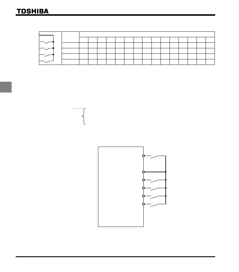
Preset-speed logic input signal example: (sink/source switching) =: With sink settings
O: ON -: OFF (Speed commands other than preset-speed commands are valid when all are OFF)
Terminal
Preset-speed
1 2 3 4 5 6 7 8 9 10 11 12 13 14 15
S1-CC - - - - - - -
S2-CC - -- -- --
R-CC - - - ----
VI-CC - - - - - - -
☆ Terminal functions are as follows.
Terminal S1 ............. Input terminal function selection 3A (S1)
=10 (Preset-speed command 1: SS1)
Terminal S2 ............. Input terminal function selection 4A (S2)
=12 (Preset-speed command 2: SS2)
Terminal R ............... Input terminal function selection 2A (R)
=14 (Preset-speed command 3: SS3)
Terminal VI Analog/ logic input selection (VI)
=2 (logic input)
Input terminal function selection 5 (VI)
=16 (preset-speed command 4: SS4)
☆ In the default settings, SS3 and SS4 are not assigned. Assign SS3 and SS4 to R and VI with input
terminal function selection. VI terminal must also be set for switching to logic input.
F (Forward run)
CC
VI
S2
R
S1
Forward
Preset-speed 1 (SS1)
Preset-speed 3 (SS3)
Preset-speed 4 (SS4)
Preset-speed 2 (SS2)
Common
*1
*1: When VI terminal is used for the logic input terminal, refer to section 2.3.2 (page B-10) for details.
CC
S1
S2
VI
R
[ Example of a connection diagram ]
(with sink settings)

 Loading...


