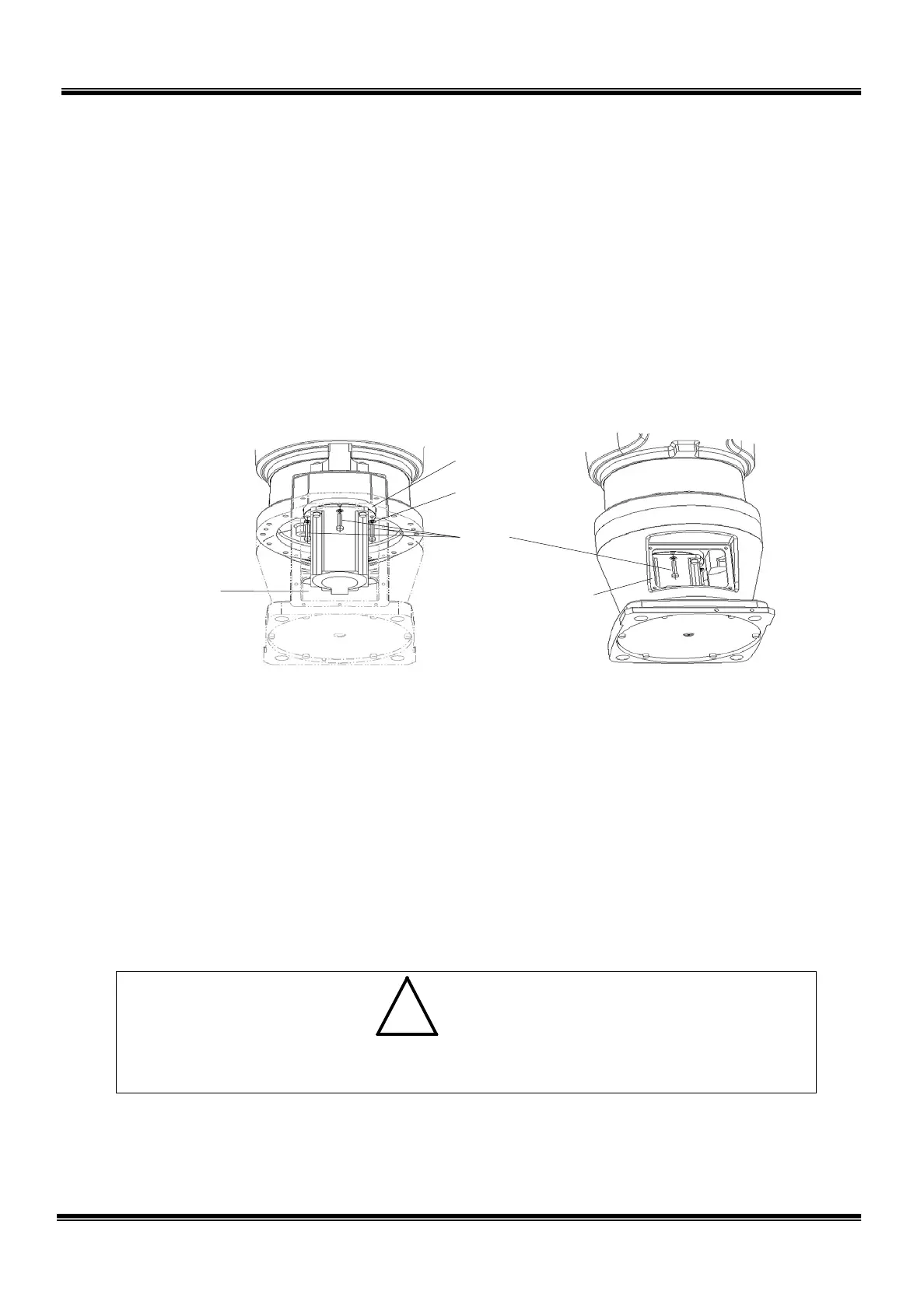
Hole for mounting the
cover also serving as
the battery box cover.
Insert the wrench from
this hole and
remove
one (1) bolt in the base.
Base opening
Connector panel side
2.5.3 Dismounting Axis 1 Motor
1) Disconnect the two (2) covers attached to the base. (See Para. 2.4.3.)
2) Disconnect connectors J1AS and J1AP (power drive cables) and connectors
J1BS and J1BP (encoder cables) of the axis 1 motor.
3) Remove the four (4) bolts (M5 × 25) securing the motor base, then draw the
motor downward. At this time, insert the hexagonal wrench key from the front
side hole where the cover also serving as the battery box cover is attached,
then remove the one (1) bolt in the base.
4) Remove the disconnected motor base from the base opening.
At this time, use a waste cloth, etc. because the input gear is grease-lubricated.
Take careful precautions not to stain the cables with grease.
5) Secure the input gear, using a vice, etc. and remove the bolt (M5 × 10) at the
shaft end. When securing the input gear, use a shock-resistant material such
as waste cloth in such a manner that the tooth top or tooth surface is not cut or
scratched. After removing the bolt, draw the washer and input gear upward.
Be sure to remove the key and “O” ring.
• When dismounting the input gear, DO NOT knock it with excessive force.
Otherwise, the encoder may be damaged.
STE 85306
– 32 –
 Loading...


