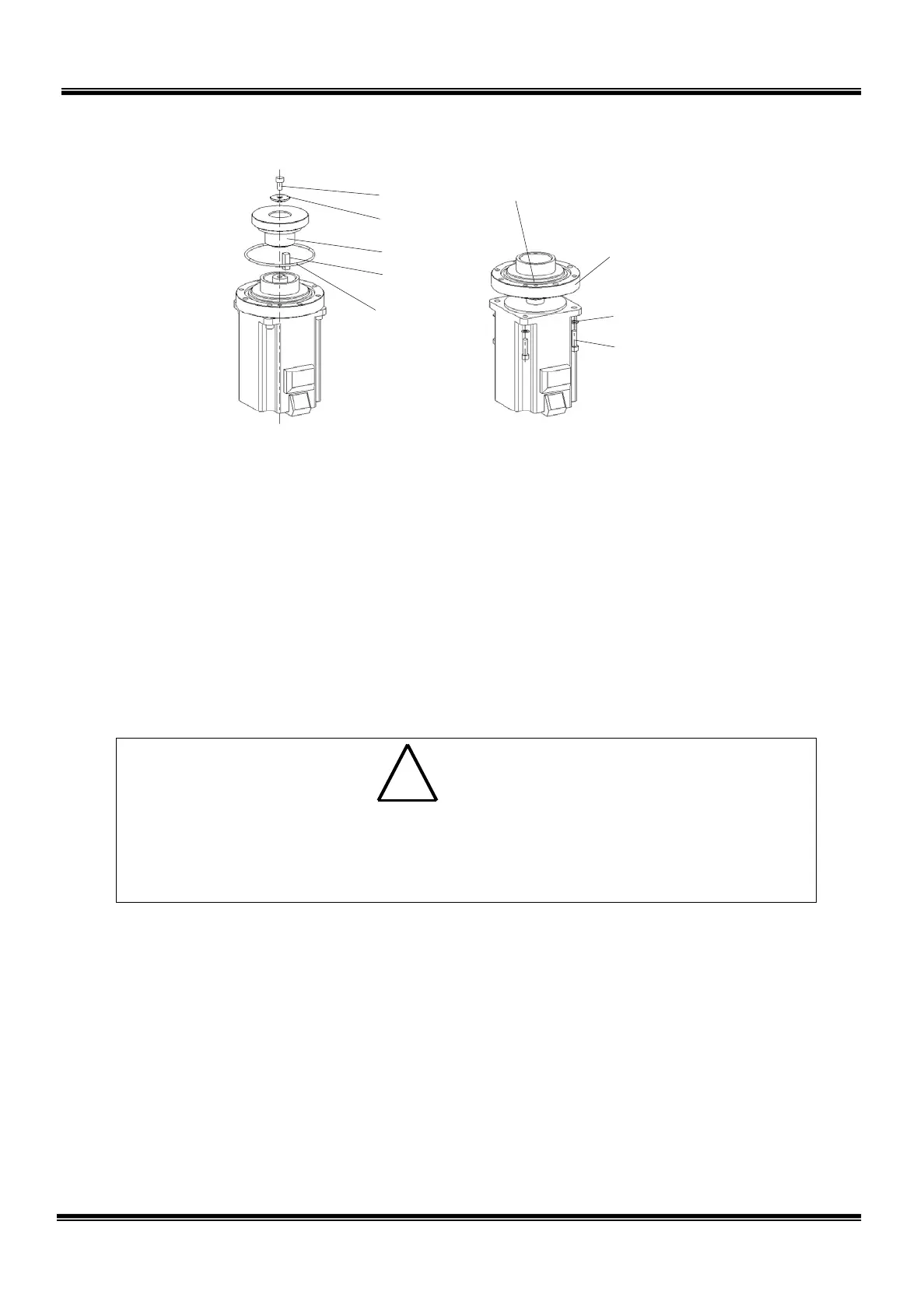
Tap for disassembly (M4; 2 places)
6) Remove the four (4) bolts (M5 × 20) securing the motor.
7) Disengage the motor from the motor base. As the motor set surface is applied
with liquid gasket, disengage them, using the taps for disassembly (M4, two (2)
places).
2.5.4 Mounting Axis 1 Motor
1) Perform key alignment, using the new motor and input gear. At this time, no
clearance should exist between the motor shaft and input gear.
• Perform key alignment very carefully. If there is a clearance between the
motor shaft and input gear, an abnormal noise may be heard at the time of
operation. Also, positioning accuracy will drop and the life of the parts will
shorten.
2) Mount the motor on the motor base with four (4) bolts (M5 × 20). At this time,
apply the liquid basket to the motor set surface.
3) Mount the input gear and key, then secure them with the bolt (M5 × 10) and
washer. Secure the input gear, using a vice, etc. and tighten the bolt (M5 × 10)
at the shaft end. When securing the input gear, use a shock-resistant material
such as waste cloth in such a manner that the tooth top or tooth surface is not
cut or scratched.
STE 85306
– 33 –
 Loading...


