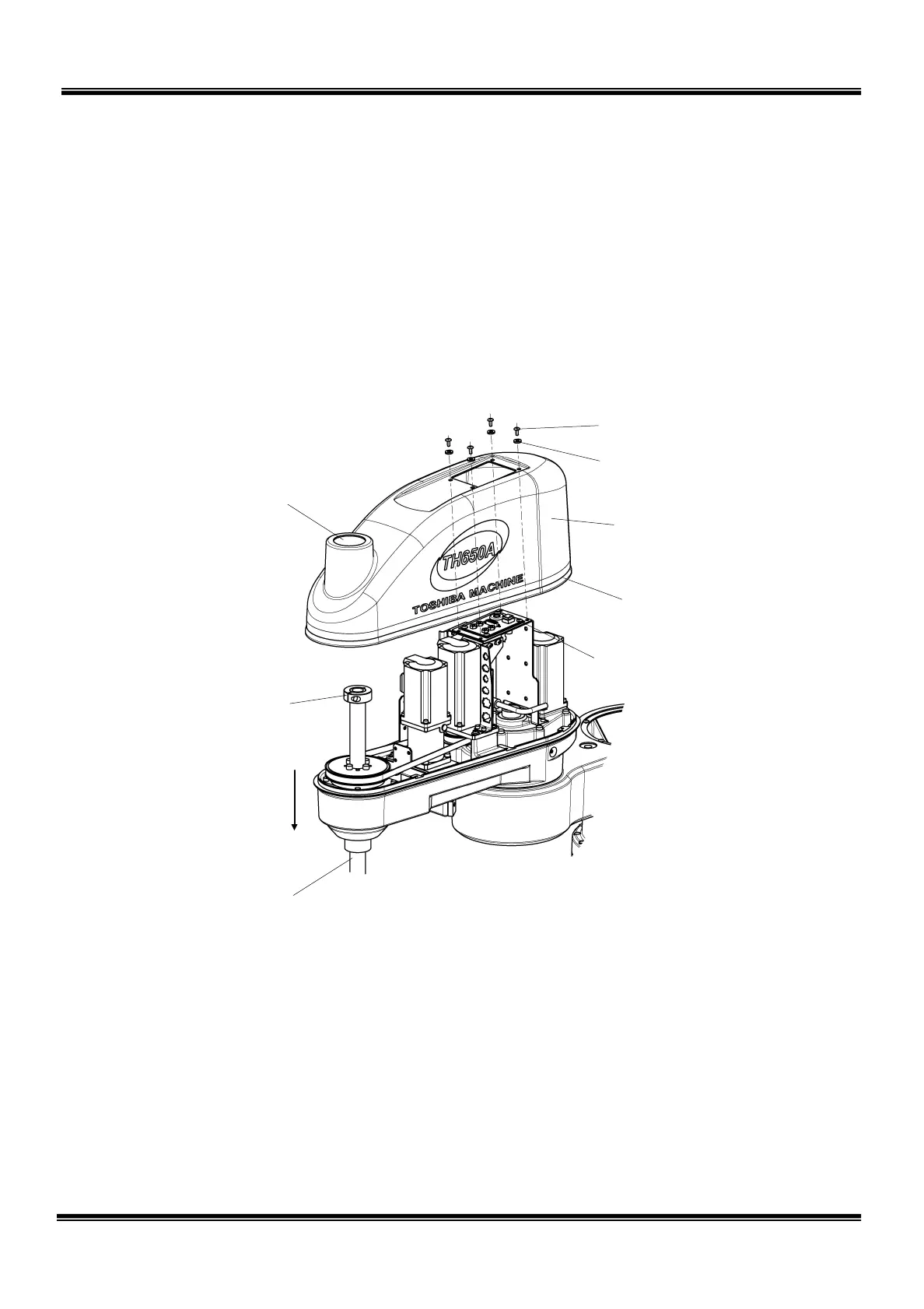
2.4.1 Arm 2 Cover
The arm 2 cover is secured to the cover set bracket with four (4) cross truss head
screws (M4 × 10). As the arm 2 cover is inserted into the arm 2, it can be lifted
once the screws are removed. The inserted unit may not be disengaged easily,
however. When this happens, it is recommended that the axis 3 be lowered
beforehand until the ball screw stopper enters the cover so that you can hold the ball
screw hole (“A” part in Fig. 2.7) when lifting up the cover. The packing attached to
the cover can be disconnected together with the cover.
Fig. 2.7 Arm 2 cover
Nylon washers are used to protect the cover. When mounting the cover, be sure to
set them. Also, take utmost care not to turn up the packing attached under the
cover. After the cover is mounted, manually move up and down the ball screw
shaft spline while pressing the brake OFF switch, and make sure that the ball screw
hole will not interfere with the ball screw stopper.
“A” part).
Lower the axis 3
beforehand.
STE 85306
– 26 –
 Loading...


