2.3 Layout of Robot Components and Drive Mechanism
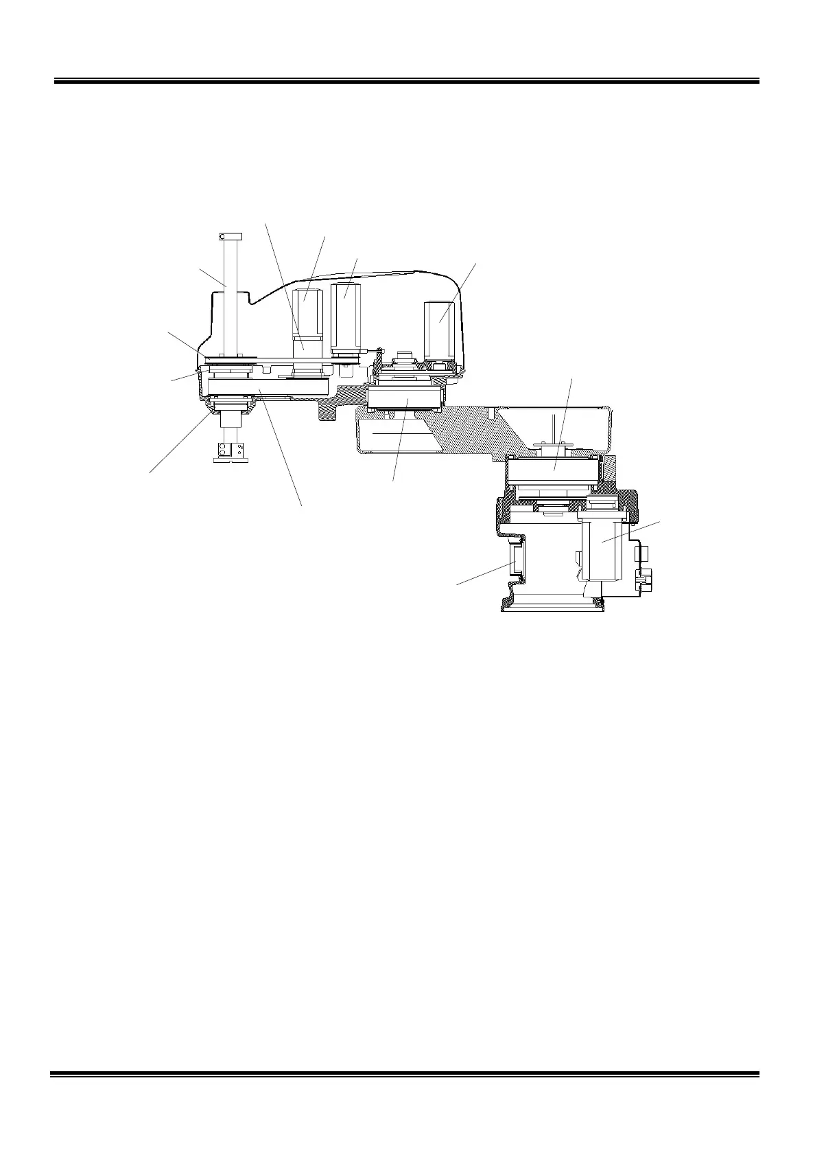
The layout of the robot mechanical components is shown in Fig. 2.6.
Fig. 2.6 Layout of robot mechanical components
The drive mechanism of each axis is described below.
a) Axis 1
The axis 1 AC servo motor is mounted on the base.
The motor revolution is input to the reduction gear via the input gear and
reduction center gear. The output of the reduction gear directly controls the arm
1 motion.
b) Axis 2
The axis 2 AC servo motor is mounted on the axis 2 arm.
The motor revolution is input to the reduction gear via the input gear and
reduction center gear. The output of the reduction gear directly controls the arm
2 motion.
on gear
STE 85306
– 23 –
 Loading...


