Turn each cable connector by
hand and make sure that it is
tightened completely.
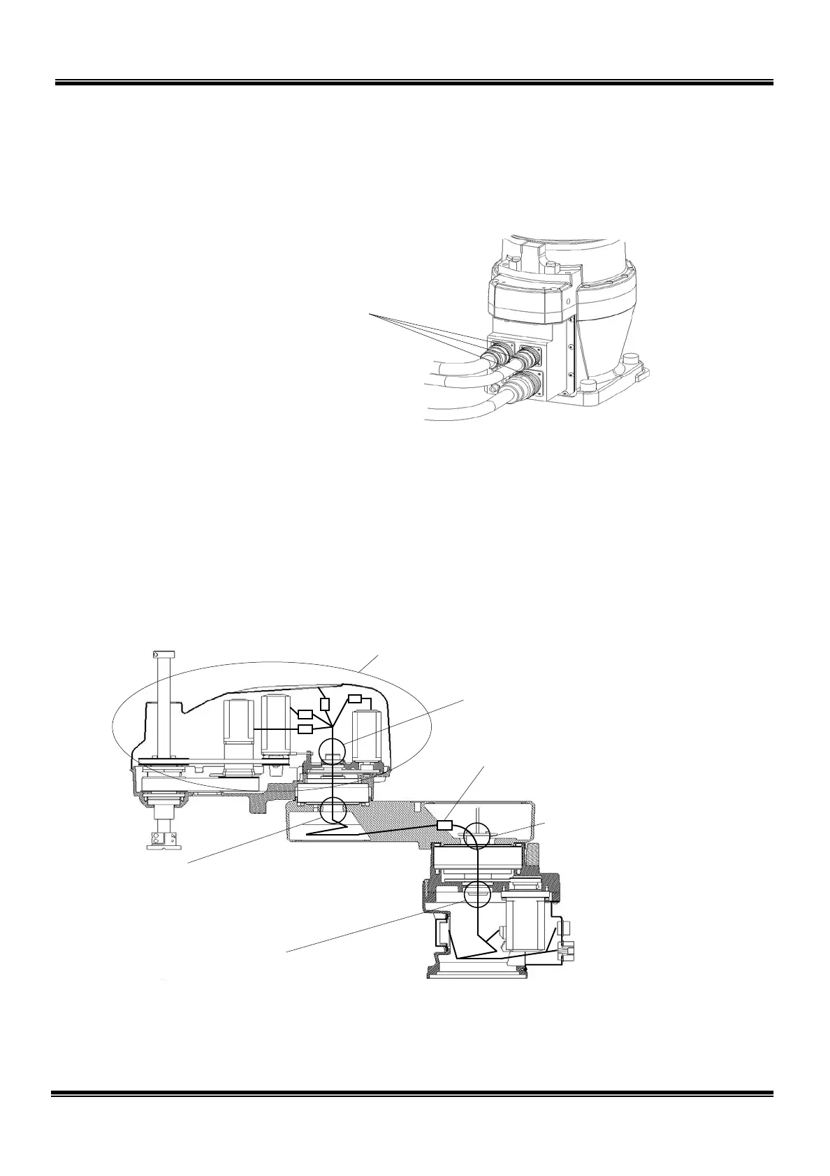
2.2.2 Check of Each Connector for Clamping
Make sure that the cable connectors connected to the robot main base are tightened
completely. If loosened, tighten them completely.
Fig. 2.4 Base connectors
2.2.3 Check of Each Cable and Air Tube for Abrasion
Disassemble the arm 2 cover and arm 1 covers (two (2) different covers are
provided) and make sure that each cable and air tube are not worn out, broken or
cracked. Especially, take careful precautions to inspect the vicinity of the cable
outlets of the axis 1 joint and axis 2 joint.
For how to disconnect the covers, see Para. 2.4.
Fig. 2.5 Cable and air tube check points
Base interior
The cable is wound spirally.
Check the vicinity of the center shaft inlet for abrasion.
The air tube is not wound spirally.
Connector-connected in the axis 1 arm.
T
he air tube is connected by means of
Axis 1 joint outlet
Check the vicinity of the center
shaft outlet for abrasion.
Arm 1 interior
The cable are wound spirally.
Check the vicinity of the center shaft inlet for abrasion.
d spirally.
Axis 2 joint outlet
Check the vicinity of the center
shaft outlet for abrasion.
Arm 2 cover interior
Perform check throughout.
STE 85306
– 21 –
 Loading...


