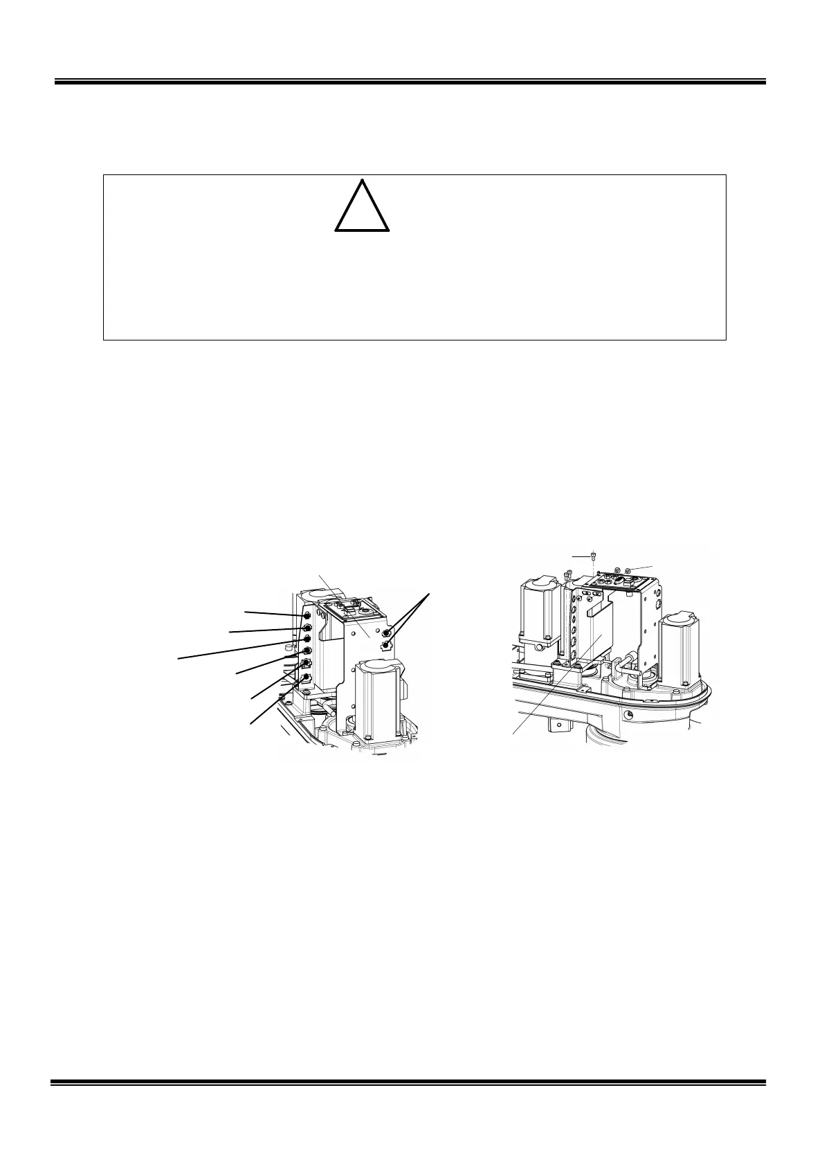
J4BS-J4BP)
Axis 3 power drive
(J3AS-J3AP)
J4AS-J4AP)
J3BS-J3BP)
2.5.7 Dismounting Axis 3 Motor
• The axis 3 motor is provided with a brake. At replacement of the axis 3 motor,
this brake becomes inoperative. Before starting the work, therefore, move
down the ball screw spline to the lower limit. Otherwise, the shaft will drop due
to the dead weight of the shaft or workpiece, and your hand or finger may be
caught.
1) Remove the arm 2 cover. (See Para. 2.4.1.)
2) Disconnect all connectors for the axes 3 and 4, which are connected to the
connector panel. For the connector layout, see the figure below.
3) Remove the four (4) cross truss head screws (M4 × 6) securing the cover
bracket and connector panel, and the three (3) bolts (M4 × 8) securing the
connector panel to dismount the connector panel.
4) Remove the axis 3 tension adjustment bolt (M4 × 35) and loosen the flange
head bolts (M5 × 16) securing the axis 3 motor base to cancel the axis 3 timing
belt tension. Then draw out the motor together with the motor base upward.
5) Secure the axis 3 motor pulley, using a vice, etc. and remove the bolt (M4 × 8)
at the shaft end. When securing the pulley, take careful precautions not to
distort the pulley flange and not to damage the pulley.
6) After removing the bolt, draw out the washer, pulley and key.
7) Remove the four (4) bolts (M4 × 16) securing the motor, and separate the axis 3
motor from the motor base.
STE 85306
– 41 –
 Loading...


