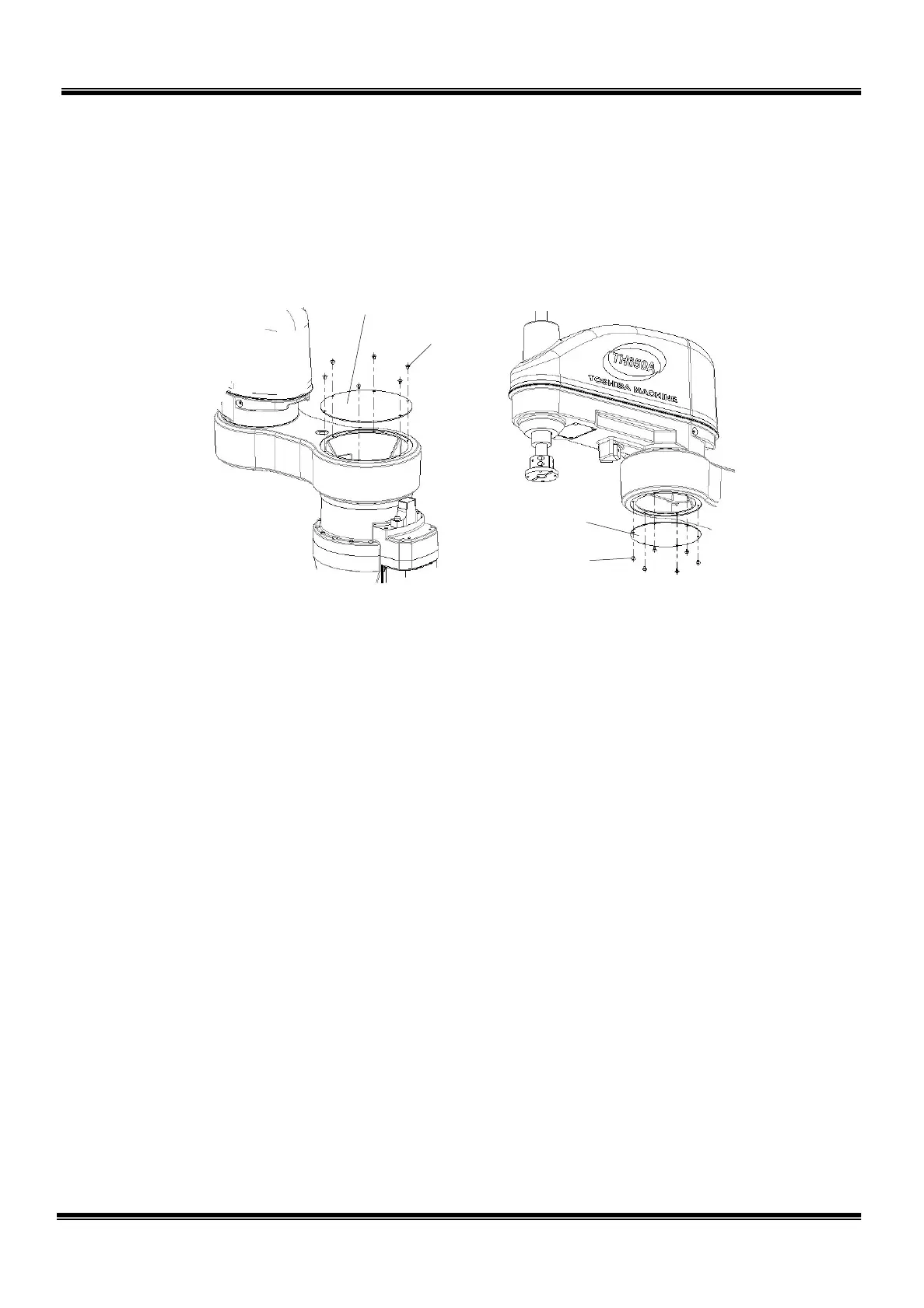
2.4.2 Arm 1 Covers
The arm 1 covers are provided on top of the axis 1 (arm cover 1) and under the axis
2 (arm cover 2). Each cover is secured to the arm 1 with six (6) cross truss head
screws (M4 × 6).
Fig. 2.8 Arm 1 covers
2.4.3 Base Covers
In all, two (2) base covers are provided; the cover also serving as the connector
panel cover and cover also used as the battery box cover.
The former cover is secured to the base with nine (9) cross truss head screws (M4 ×
6) and four (4) hexagon socket head cap screws (M4 × 10).
The latter cover is secured to the base with four (4) cross truss head screws (M4 ×
6). Though each cover can be disconnected when the clamp bolts are removed, it
is connected to the cables inside. DO NOT pull the cover by force.
The cover also serving as the connector panel cover is provided with packing.
Take careful precautions when handling this cover.
STE 85306
– 27 –
 Loading...


