124
NOTE: To determine the appropriate shim, start
with the thickest shim and install the snap ring. If the
snap ring will not fit in the groove, remove the shim
and install the next size smaller shim. Continue until
the snap ring can be installed.
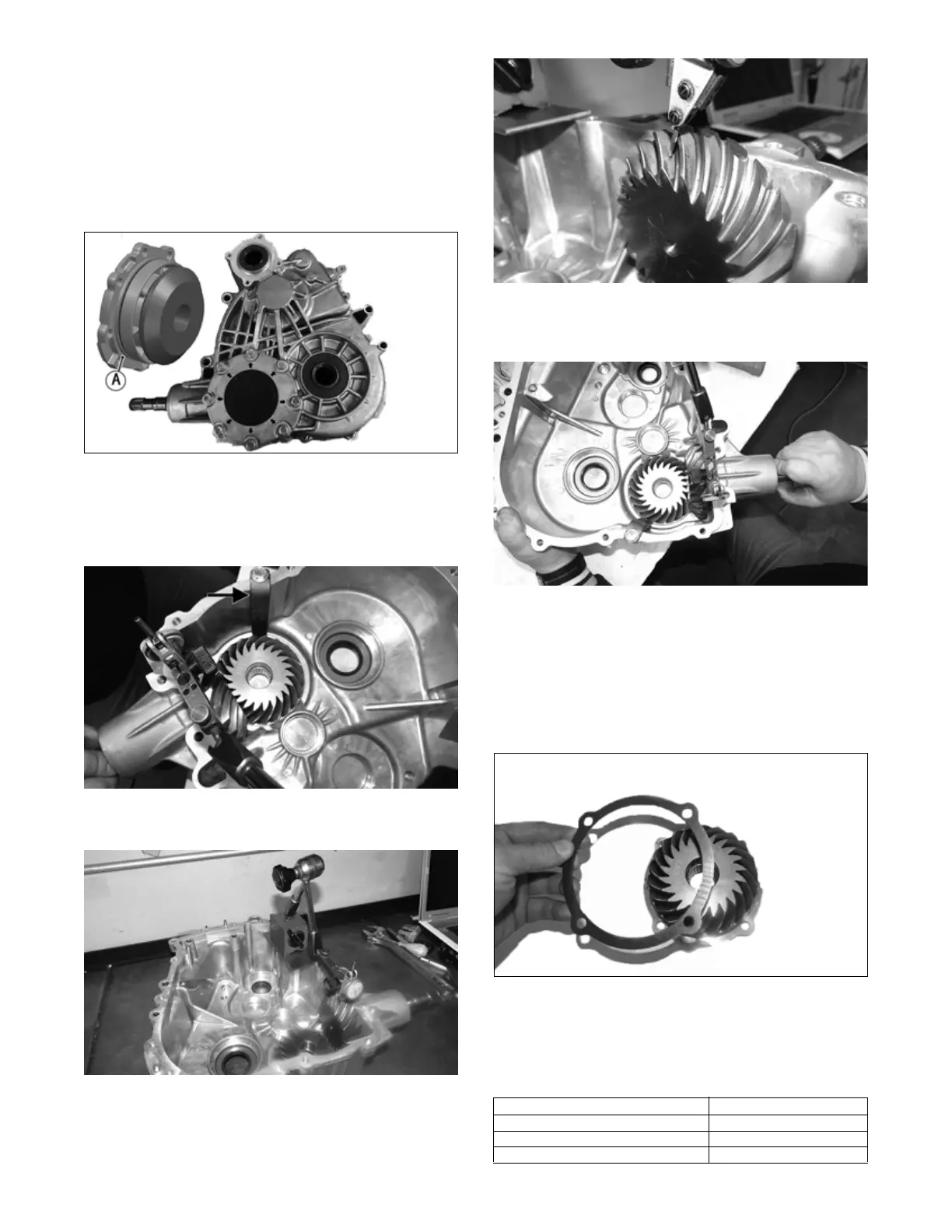
2. With the appropriate shim in place and a new O-ring
(A) coated with molybdenum grease, install the pin-
ion gear assembly into the case half and secure with
the eight screws. Tighten to 20 ft-lb (27.2 N-m).
NKL001B
NOTE: To determine the appropriate shim, proceed
to step 3.
3. Using an appropriate tool, lock the pinion gear in
place.
TA124A
4. Mount a dial indicator so the tip is contacting a tooth
on the pinion shaft.
TA096
TA095
5. While pushing in on the front output shaft, and while
rocking the shaft back and forth and note the maxi-
mum backlash reading on the gauge.
TA125
6. Acceptable backlash range is 0.076-0.241 mm
(0.003-0.0095 in).
NOTE: If backlash measurement is within the
acceptable range, no correction is necessary.
7. If backlash measurement is less than specified,
remove the existing shim and install a new thicker
shim (from shim kit).
TA102
8. If backlash measurement is more than specified,
remove the existing shim and install a thinner shim.
NOTE: Continue to remove, measure, and install
until backlash measurement is within tolerance. Note
the following chart:
Backlash Measurement Shim Correction
Under 0.076 mm (0.003 in) Increase Shim Thickness
At 0.076-0.241 mm (0.003-0.0095 in) No Correction Required
Over 0.241 mm (0.0095 in) Decrease Shim Thickness