125
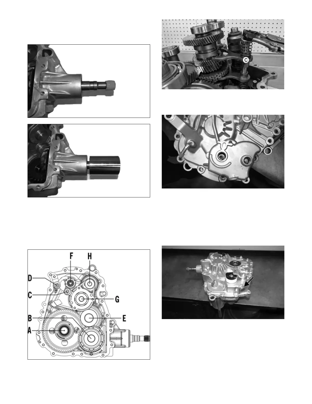
9. Tape the splined portion of the pinion shaft to protect
the seal; then using an appropriate seal installer,
install the front output seal so it seats fully past the
chamfer of the case.
TA129
TA130
ASSEMBLING HALVES
1. Reassemble components in proper location in lower
half, with the shift shaft rail (C) last. Position bottom
shift fork assembly shaft and pull up on shaft with
tool that is smooth or wrapped to prevent scaring of
shaft. Guide the forks in bottom and top grooves of
reverse shaft (G).
TA139
OHA128A
2. Apply a coat of Loctite 5699 to the case; then ensur-
ing the shift shaft (O-ring lightly coated with grease)
and shift rail are correctly seated, install the cover.
TA068
NOTE: It will be necessary to tap the cover onto the
case using a rubber mallet. Ensure the alignment pins
are properly oriented.
3. Secure the cover with the cap screws and tighten to
20 ft-lb (27.2 N-m).
4. Install the detent with spring and O-ring. Tighten to
20 ft-lb (27.2 N-m).
TA012A
5. Install gear position switch and speed sensor (see
Electrical System section).
6. Add approximately 1.2 quarts of Synthetic Transaxle
Fluid with EP to the transaxle. Verify fluid is level
with the bottom threads of the fill plug hole; then
install the fill plug and tighten to 16 ft-lb (21.8 N-m).
INSTALLING TRANSAXLE
1. Using new lock nuts, secure the bracket to the rear of
the transaxle. Tighten to 38 ft-lb (51.7 N-m).