Pag. 12
PMS701 HS-TR
STD version
Manutenzione freno
Brake maintenance
Replace of the Brake Discs
The brake discs unit is made of 6 steel
discs (9) and 5 friction discs (53), ordered
in an alternate way (the first one and the
last one must be smooth). Between every
couple of steel discs four elastic spacers are
inserted (66), one spacer on each locking
pin (73) (see fig 9)
Remove first the 2 retaining rings (43)
from the studs (25), then the discs pusher
device (13+75+10) and the brake disc unit.
Pull the springs (67) out from the studs
(25). Remove the aluminium reaction disc
(12).
Wash down the cartridge thoroughly, then
to assemble the parts again follow next
steps:
•
step1: insert the reaction disc (12)
•
step2: insert steel disc (9), 4 elastic
spacers (66) one spacer on each
locking pin (73), friction discs (53).
•
step3: repeat step2 for 4 times
•
step4: place last steel disc and the 2
springs (67) in the studs (25).
•
step5: insert the discs pusher device
(13+75+10) onto the pins (25), then,
pressing down all, place the 2
retaining rings (43) into the seat on
the pins (25).
Sostituzione dei Dischi Freno
Il pacco è composto da 6 controdischi (9)
e 5 dischi di attrito (53) tra loro alternati e
disposti in modo che il primo e l'ultimo
siano lisci. Tra ogni coppia di controdischi
sono inseriti 4 distanziatori elastici (66),
uno per ogni spina (73) (vedi fig.9).
Rimuovere i 2 anelli di tenuta (43) sulle
spine (25) e quindi il dispositivo
spingidischi (13+75+10) e gli 11 dischi del
pacco freni. Togliere le molle (67) dalle
spine (25). Rimuovere il disco di appoggio
di alluminio (12).
Lavare accuratamente la cartuccia freno,
montare il nuovo pacco freni rispettando il
il seguente ordine:
•
step1: inserire disco appoggio
controdischi (12)
•
step2: inserire controdisco (9), 4
distanziatori elastici (66) uno per
spina (73), disco di attrito (53).
•
step3: ripetere lo step2 per 4 volte.
•
step4: p o siz io n a r e l’ u lt i mo
controdisco e le due molle (67) nelle
spine (25).
•
step5: inserire sulle guide (25) il
dispositivo spingidischi (13+75+10)
quindi, schiacciando il tutto inserire i
2 anelli di sicurezza (43) nelle
apposite sedi sui perni (25).
1) I numeri tra parentesi si riferiscono alla posizione
indicata nelle liste ricambi
1) Numbers in brackets refer to the parts as listed
in the spare part list
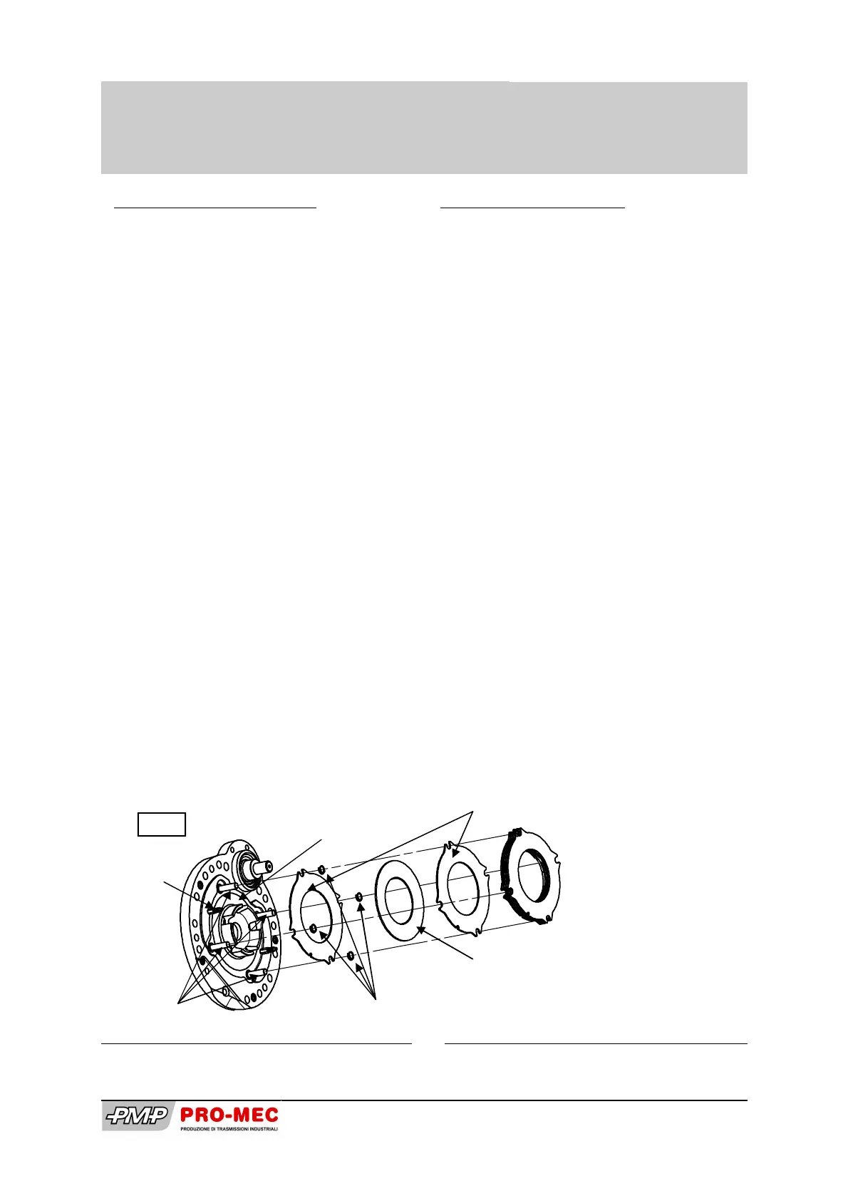
Fig 9
Controdisco di acciaio (9)
Steel disc (9)
Disco di attrito (53)
Friction disc (53)
Distanziatori elastici (66)
Elastic spacer (66)
Spine (73)
Pins (73)
Perni (25)
Studs (25)
Disco appoggio (48)
Reaction disc (48)