Connecting
Connecting the power supply
22
Hans Turck GmbH & Co. KG | T +49 208 4952-0 | F +49 208 4952-264 | more@turck.com | www.turck.com
Connect the device to the power supply according to the pin assignment shown below.
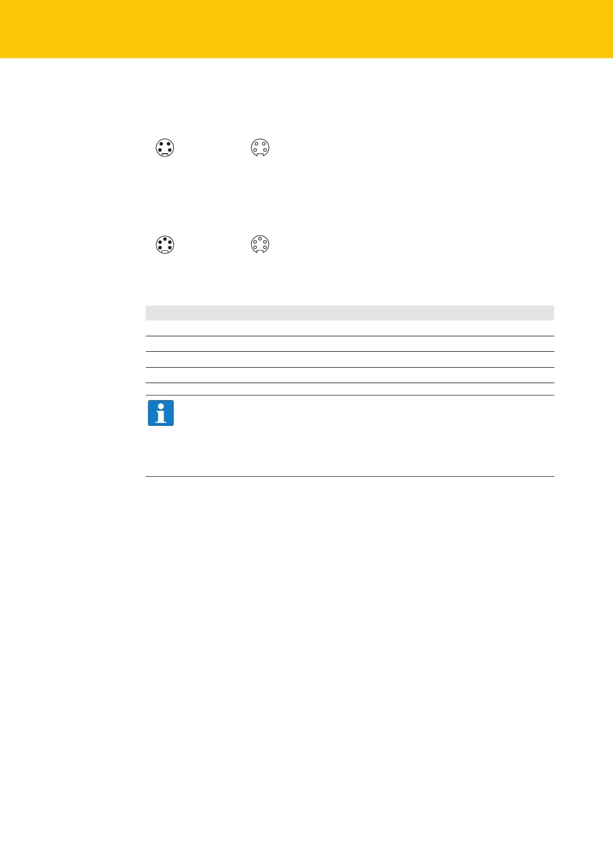
w v
1
2
3
4
1 RD = 24 VDC V2
2 GN = 24 VDC V1
3 WH = GND V1
4 BK = GND V2
1
2
3
4
X1 X2
Fig.16: TBEN-L4-PLC-… – Pin assignment power supply connectors
1 BK = GND V2
2 BU = GND V1
3 GNYE = FE
4 BN = 24 VDC V1
5 WH = 24 VDC V2
3
4
5
2
1
w v
3
4
5
2
1
X1 X2
Fig.17: TBEN-L5-PLC-… – Pin assignment power supply connectors
Connector Function
X1 Power feed
X2 Continuation of the power to the next node
V1 System voltage: Power supply 1 (incl. supply of electronics)
V2 Load voltage: Power supply 2
NOTE
The system voltage (V1) and the load voltage (V2) are fed in and monitored separ-
ately. In case of an undercut of the admissible voltage, the connectors are switched-
off according to the module's supply concept. In case of an undervoltage at V2, the
LED PWR changes from green to red. In case of an undervoltage at V1, the LED PWR
is turned off.

 Loading...


