V02.00 | 2019/11
21
6 Connecting
6.1 Connecting the modules to Ethernet
For the connection to Ethernet, the device has two 4-pin D-coded M12 connectors. The max-
imum tightening torque is 0.6 Nm.
Fig.12: M12 Ethernet connector
Connect the device to the field bus according to the pin assignment shown below.
v
4
1
3
2
P1, P2
1 = TX +
2 = RX +
3 = TX –
4 = RX –
flange = FE
Fig.13: Pin assignment Ethernet connectors
NOTE
The behavior of the Ethernet Interfaces depends on the parameterization of the
TBEN-L...-PLC-.... The connectors operate in switch mode as autocrossing switches
with one IP address. In Dual MAC Mode, the Ethernet connectors are treated as sep-
arate Ethernet ports with two separate MAC and IP addresses. The TBEN-L...-PLC-...
can thus be a node in two separate Ethernet networks in Dual MAC mode.
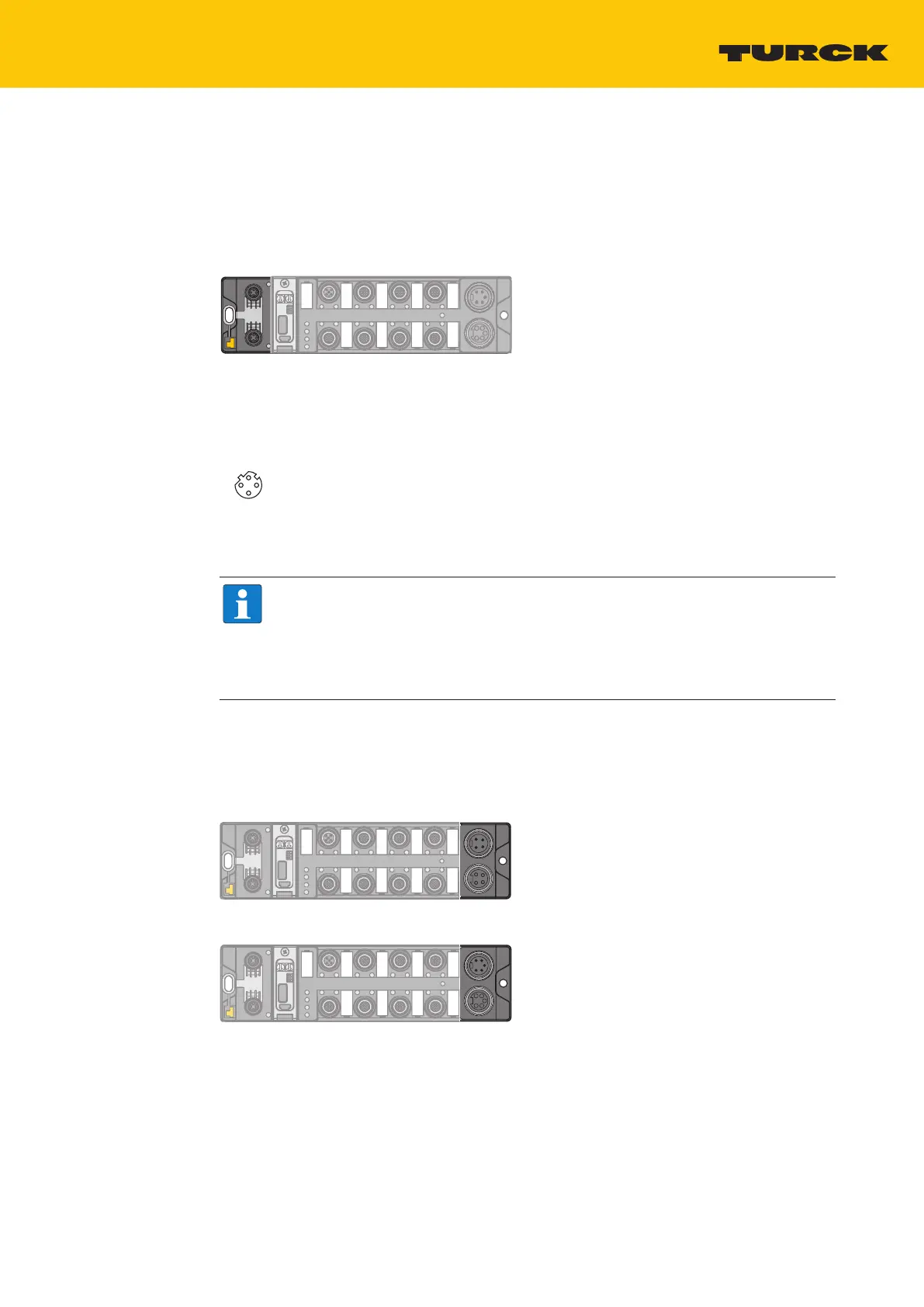
6.2 Connecting the power supply
For the connection to the power supply, the device has two 5-pin 7/8" connectors. The power
supply connectors are designed as 4-pole (TBEN-L4-PLC) or 5-pole (TBEN-L5-PLC) 7/8" connect-
ors. V1 and V2 are galvanically isolated. The maximum tightening torque is 0.8 Nm.
Fig.14: 7/8’’ connector for connecting the supply voltage (TBEN-L4-PLC-…)
Fig.15: 7/8’’ connector for connecting the supply voltage (TBEN-L5-PLC-…)

 Loading...


