Connecting
USB host port
24
Hans Turck GmbH & Co. KG | T +49 208 4952-0 | F +49 208 4952-264 | more@turck.com | www.turck.com
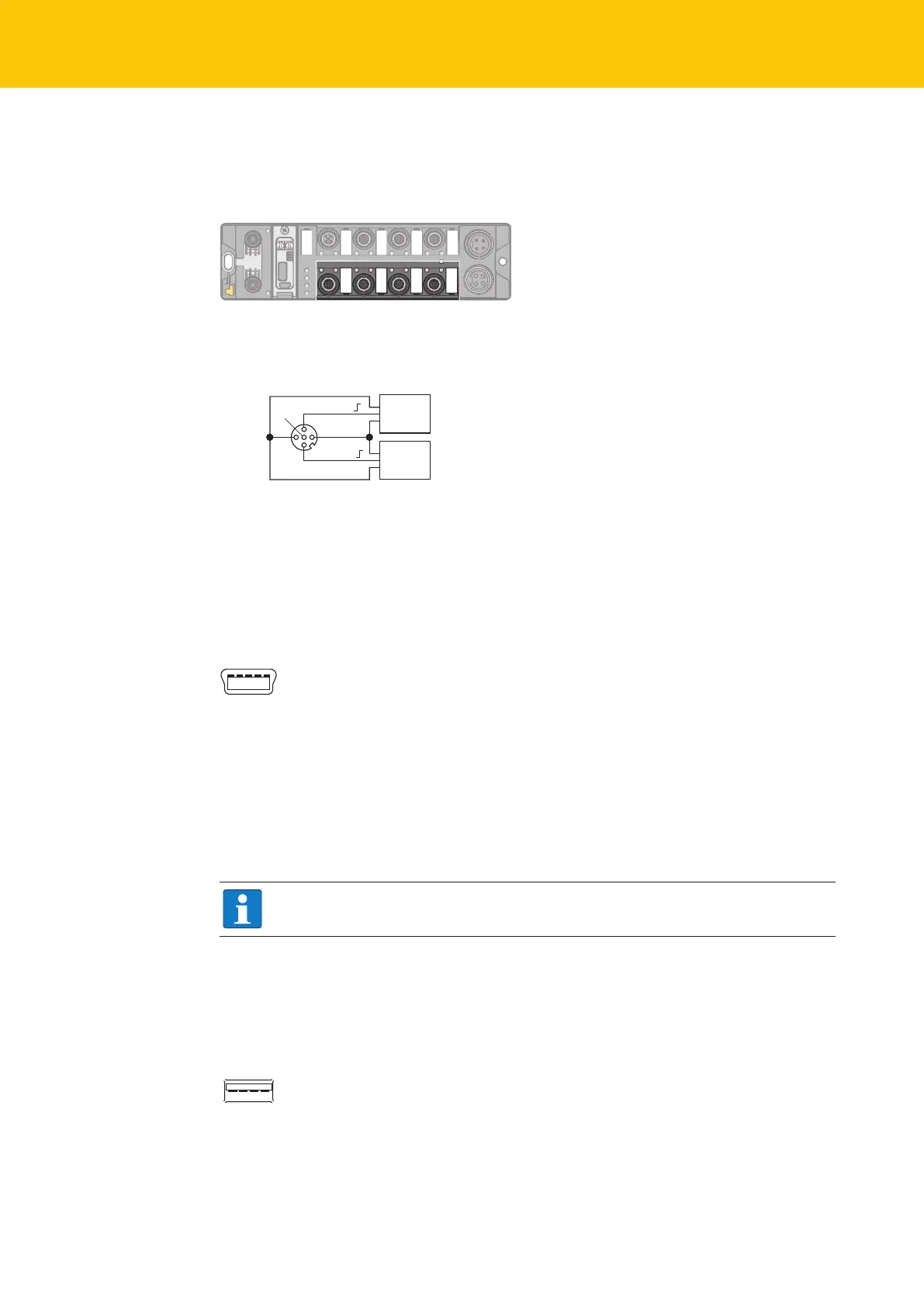
6.5 Connecting digital sensors and actuators
The device has four 5-pin M12 connectors for connecting digital sensors and actuators. The
maximum tightening torque is 0.8 Nm.
Fig.23: M12 connector for connecting digital sensors and actuators
Connect the sensors and actuators to the device according to the figure shown below.
5 FE
4 BK
1 BN +
3 BU –
3 BU –
2 WH
v
C2…C3
Sensor
or
Actuator
Sensor
or
Actuator
Fig.24: Connectors for digital sensors and actuators - wiring diagram
6.6 Using the USB device port
The USB device port is designed as a mini USB B socket and can be used as a service interface
for the device DTMs and as a programming interface for CODESYS.
1 2 3 4 5
v
1 = 5 VDC
2 = D –
3 = D +
4 = n.c.
5 = GND
Fig.25: USB device port
RNDIS driver
The RNDIS driver for the USB device port is installed automatically during the DTM installation
in PACTware™. After the DET installation, the USB device port is shown as additional Ethernet
port in the DTM.
NOTE
Use the interface BL Service Ethernet in the DTM for the connection to the device.
6.7 USB host port
The USB host port is designed as a CODESYS 2.0-A socket and is used to connect USB memory
sticks for program backup, program recovery, firmware update and data synchronization.
1 = 5 VDC
2 = D –
3 = D +
4 = GND
1 2 3 4
v
Fig.26: USB host port

 Loading...


