5-7
Fig. 5-16 1st stage
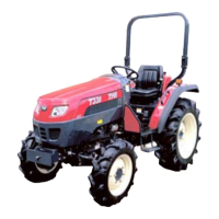
2nd stage:
At the moment when both the friction surfaces come
into contact,the ring turns by as much as the surplus
space in hub(2) for block pin(3)as shown in Fig.5-5
Fig.5-17 Block-pin
3rd stage:
When hub(2)is pushed further,the tapered surface
in the hole of the hub and the tapered surface on
the block pin are pressed tightly against each
other,this pushes synchro-ring(4) against
synchro-cup(5).Consequently,as shown Fig.5-
6,the synchro-ring and the synchro-cup are
pressed more tightly against each other by the
resultant turning force of the rear wheel and the
thrust of the shifter.Ultimately,the revolving
speeds of the synchro-ring and the synchro-cup
become the same.
(1)Thrust
(2)Resultant force
(3)Turning force
Fig. 5-18 Synchro-ring and cup
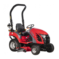
4th stage :
When synchro-ring(4) and synchro-cup(5)
reach the same speed,the friction force
disappears.Then the resistance between
hub(2)and block pin(3) also disappears to allow
the hub to clear the groove on the block pin and
to sit on the large diameter area of the pin. At
the same time,thrust piece(6) which has a
tapered shape and hub(2) advance smoothly on
the pin to complete the meshing between
spline(8) of the hub and spline(13) of the gear.
Fig. 5-19 Complete Synchro-ring and cup
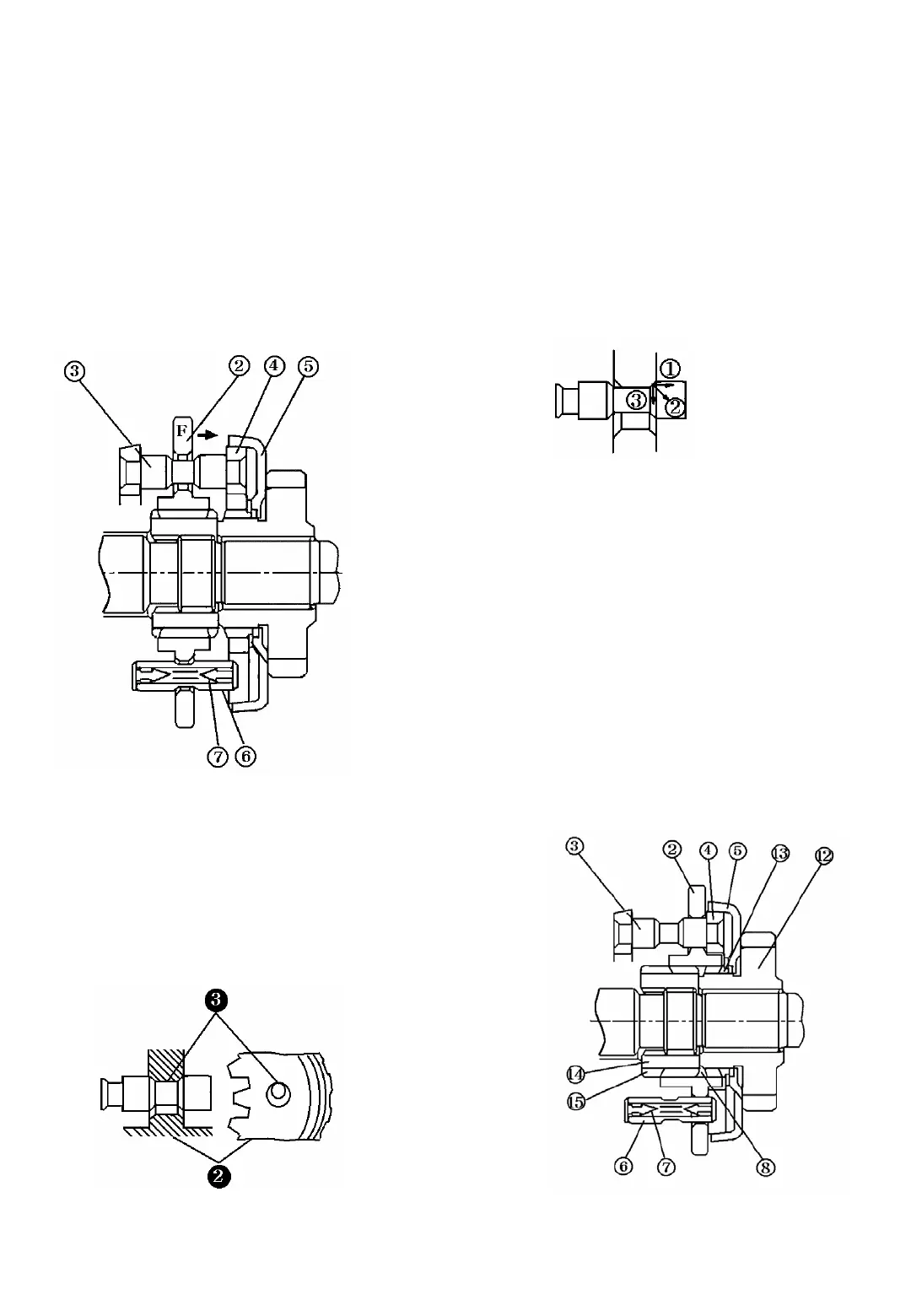
1st stage:
When force(F) is applied to shifter(1)
through the gear shift lever,hub(2) is pushed
in the direction of the arrow.Following
movement of the hub,other parts such as
block pin(3), synchro-ring(4),and thrust
piece(6) also move in the same direction by
means of spring(7), without allowing the
hub to clear the groove in thrust piece(6)
until such time as the friction surface of
synchro-ring (4)comes into contact with the
friction surface of synchro-cup (5).