5-6
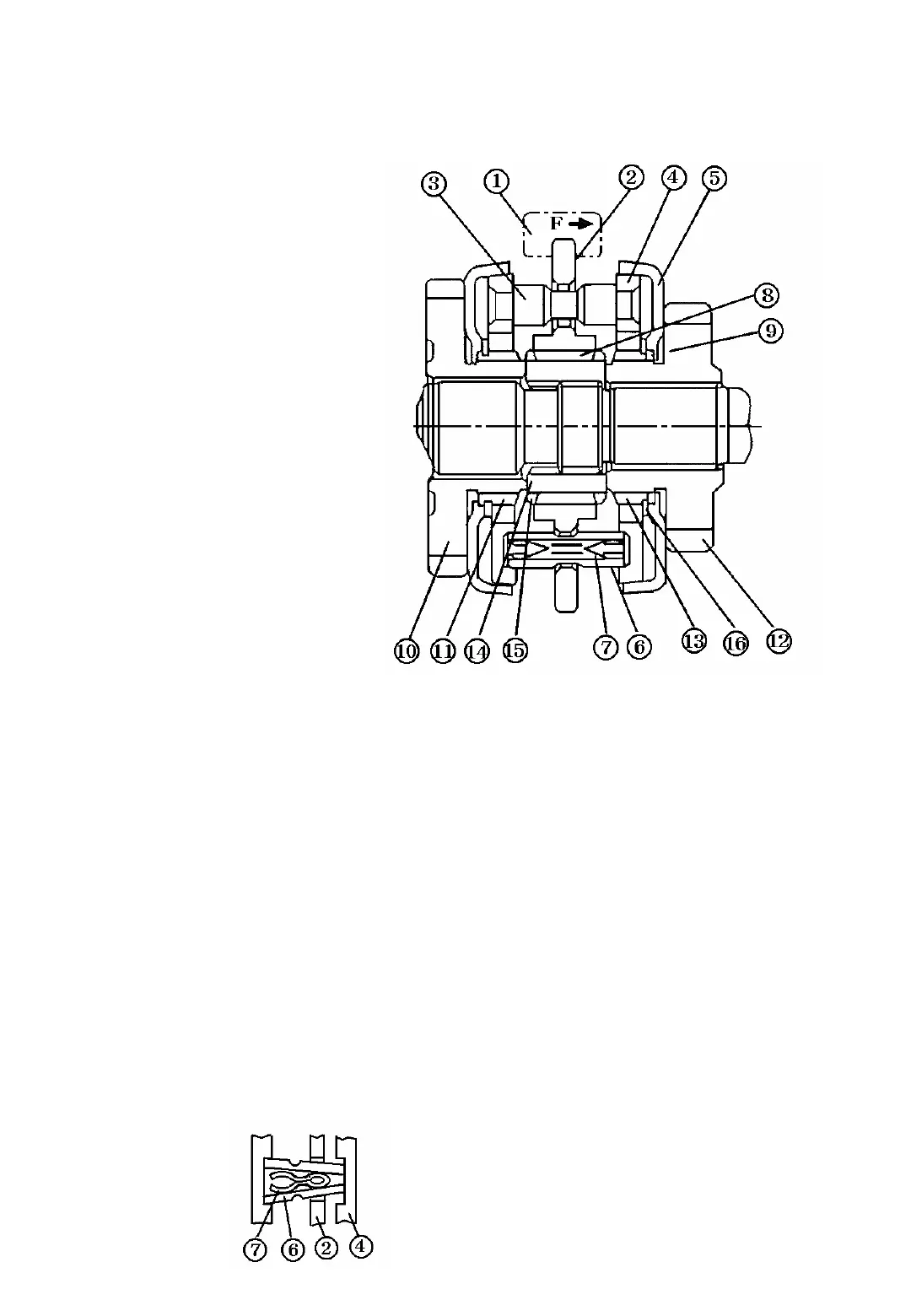
5. CONSTRUCTION AND FUNCTION OF THE SYNCHROMESH MECHANISM
1) Construction
①Shifter
②Hub
③Block pin
④Synchro-ring
⑤Synchro-cup
⑥Thrust piece
⑦spring
⑧spline of hub(2)
⑨spline of synchro-cup(2)
⑩constant mesh gear
⑪spline of gear(10)
⑫constant mesh gear
⑬Spline of gear(12)
⑭Spline hub
⑮Spline of spline hub(14)
16.Snap ring C(for shaft)
The synchromesh mechanism includes the
components staged below
Synchro-hub
The synchro-hub is composed of the hub(2),
block pin(3),synchro-ring(4),thrust piece(6),and
spring(7).Synchro-ring(4)has a conical friction
surface on its circumstance.Block pin(3)
prevents hub(2) from sliding until the torque,
imposed upon the pin due to the speed
differential caused when shifting gears,disappears.
Thrust piece(6)is composed of an outer split pin
and an inner and is held together as one unit by
the expansion force
of the spring.
It has a tapered
shape as shown
in Fig.5-15
Fig.5-14 Synchromesh
Synchro-cup
It has a conicial friction surface which forms a
pair with synchro-ring(4).It meshes with the
gears(10) and (11) through the splined part.
2) Function principles(operating procedures)
The synchromesh mechanism operates in the 4
stages mentioned below to complete the
transmission from NEUTRAL to
ENGAGEMENT
when the hub is position to side and also serves
as a lock pin to keep the synchro mechanism
engage.
Fig.5-15