1.1 DISASSEMBLY
(1) Removal of input shaft and related parts separate the engine from the front transmission referring to the
paragraph 3 of SECTION 4. SEPARATION OF MAJOR COMPONENT in Chapter 2.
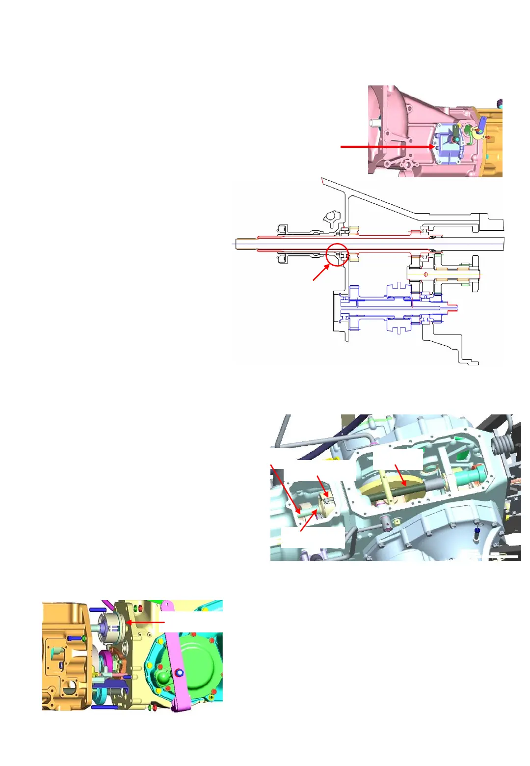
a. Remove of the reverse change cover
in the front transmission
b. Separation of the front transmission and
the spacer transmission.
Note : Be careful not to damage the seal ring
of the sleeve.
5-10
(2) Removal of the PTO clutch assembly
Separate the hydraulic cylinder case from the
rear transmission referring to the paragraph 7
of SECTION 3. SEPARATION OF MAJOR
COMPONENT in Chapter 2.
c. Separation of the reverse metal from
the spacer transmission
d. Pull out the Reverse change assembly.
(Refer to the next page)
e. Pull out spring pin and from the creep shaft.
f. Remove the snap ring C
g. Pull out the creep shaft.
Fig.5-21 Input metal and related parts
Reverse change
cover
Reverse change gears
Creep change
Oil seal
a. Remove of the hydraulic cylinder assembly
b. Remove of the cover 1 in the spacer
c. Remove of all parts around the shaft 1 and
the shaft 2.
d. Pull out the snap ring next to the PTO
clutch assembly.
e. Push the shaft 3 rearwards with holding the
PTO clutch assembly with the other hand.
Fig.5-22
Fig.5-23
PTO clutch assembly
Note : Be careful not to damage the seal ring
of the PTO clutch assembly When the PTO
clutch assembly is trouble-free, keep it
aside, without disassembling it, in a Clean,
dust- free place
Shaft 3
Snap ring
PTO clutch
Shaft 1