12x12mm
2
.VerycheapconstructiontechniquesmightuseordinarycircuitboardmateriallikeFR-4orevenair
as adielectric,but this will resultin a much largersize, typicallyintheorder of 10x10cm
2
. Figure 8shows a
typicalexampleof theradiationpatternofa16x16mm
2
ceramicpatchantenna.Thismeasurementonlyshows
theuppersphereoftheradiationpattern.Dependingongroundplanesizetherewillalsobeaprominentback
lobepresent.
Figure 8: Typical Radiation Pattern of a Patch Antenna, MuRata, Inc.
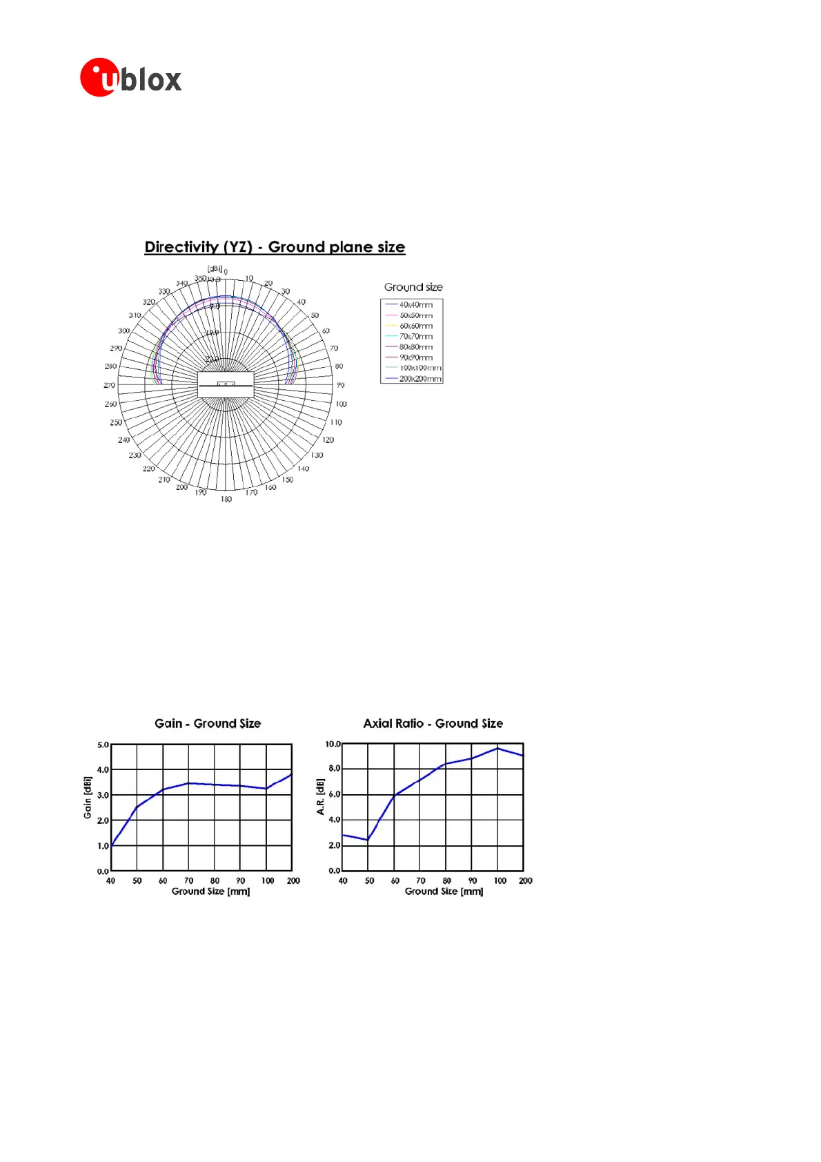
ForthespecificexampleshowninFigure 9 onecaneasilyseethattheso-calledaxialratio,therelationofmajor
tominoraxisoftheellipticalpolarizationhasaminimumatthe50mm
2
squaregroundplane.Atthispoint,the
polarization ofthe antennais closestto anidealcircularpolarization (axialratio= 0dB). Ata 100mm
2
square
ground plane size this particular patch shows an axial ratio in the order of 10dB, which is closer to linear
inthe leftgraphof
usion, the correct
groun compromis
polarization thantocircularandwillresultin respectivelosses. Thiseffectcanalsobe seen
the figure, where gain no longer increases
with increasing ground plane size. In concl
dimensions for the size of the d plane can serve as auseful e between maximum gain and
reasonablepolarizationloss.
Figure 9: Typical Gain and Axial Ratio of a Patch antenna with respect to ground plane size, MuRata, Inc.
A good allowance for ground plane size is typically in the area of 50to70mm
2
. This number is largely
independent of the size of the patch itself (when considering ceramic patches). Patch antennas with small
groundplaneswillalsohaveacertainback-lobeintheirradiationpattern,makingthemsusceptibletoradiation
comingfromthebacksideoftheantenna,e.g.multi-pathsignalsreflectedoffthe
ground.Thelargerthesizeof
thegroundplane,thelessseverethiseffectbecomes.
GPSModules-SystemIntegrationManual(SIM)(incl.ReferenceDesign) GPSFundamentals
GPS.G4-MS4-05007-A1
Page 18
 Loading...

