antennaswitha “reasonable”sizewillthereforetypicallyshow alowersensitivity comparedto a“reasonably”
sizedpatchantenna.
Ahelixantennamightresultina“moresatellitesonthescreen”situationindifficultsignalenvironmentswhen
directlycomparedwithapatchantenna.Thisisduetothefactthatthehelix willmoreeasily pickup
signalsthroughitsomnidirectionalradiationpattern.However,thepracticaluseofthesesignalsis verylimited
because of the uncertain path of the reflected signals. Therefore, the receivers can see more satellites but the
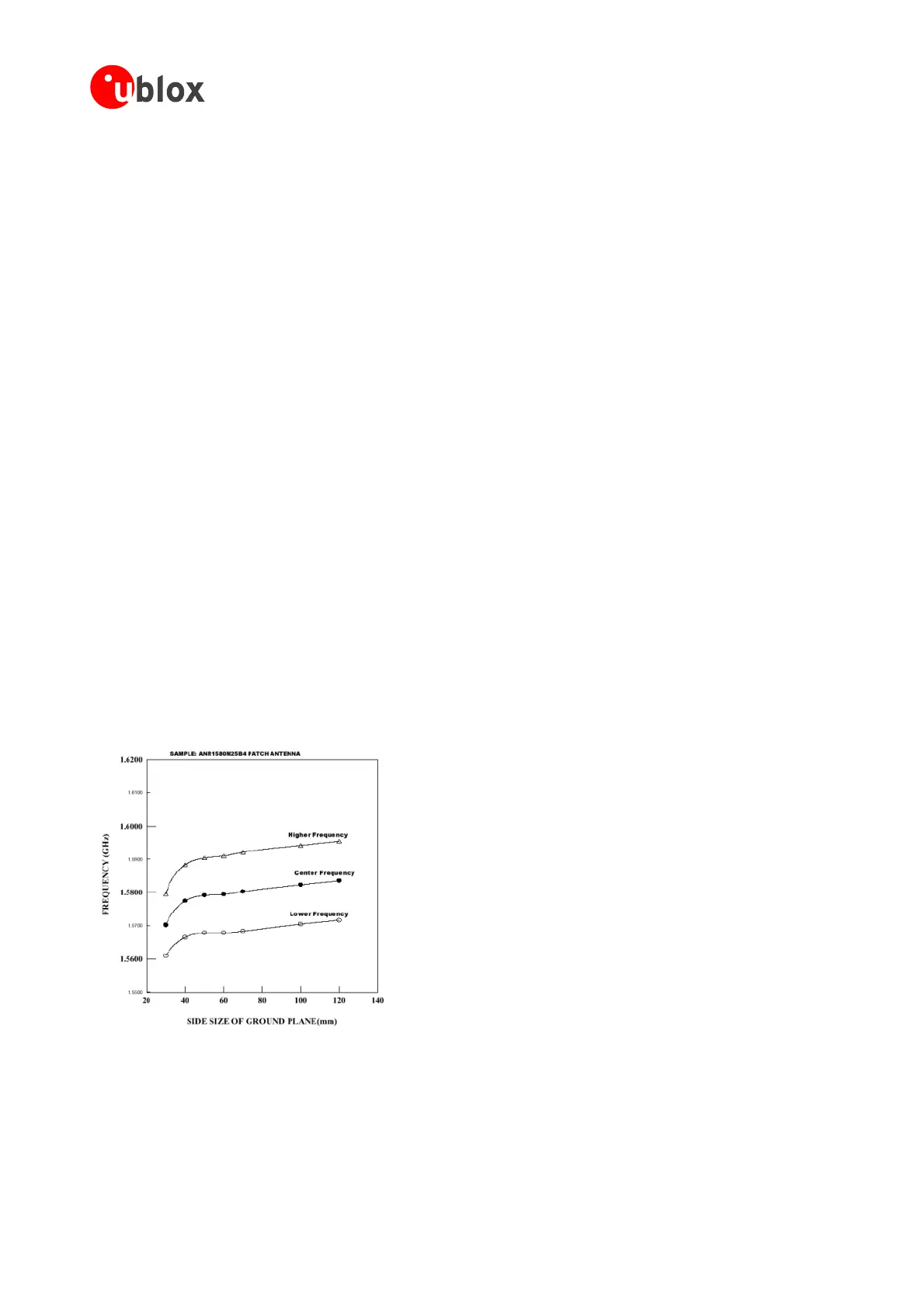
tsa50Ohmssourceimpedance. Typicallywhathappens isthatthecenterfrequency
of the antenna is shifted away from GPS frequency - usually towards lower frequencies – by some external
i asonsforthiseffectareprimarilydisturbancesin thenear fieldoftheantenna.Thiscaneither
bea groundplane,thatdoesnothavethesizeforwhichtheantennawasdesigned,oritcanbeanenclosure
rease with decreasingantennasize, making it harder to
achieveoptimumtuning.
navigationsolutionwillbedegradedbecauseofdistortedrangemeasurementsinamulti-pathenvironment.
If possibletestthe actualperformanceof differentantennatypes inareallifeenvironmentbefore starting the
mechanicaldesignoftheGPSenabledproduct.
1.5.8 Antenna Matching
AllcommonGPSantennasaredesignedfora50Ohmselectricalload.Therefore,oneshouldselecta50Ohms
cable to connect the antenna to the receiver. However, there are several circumstances under which the
matching impedance of the antenna might shift considerably. Expressed in other words, this means that the
antennanolonger presen
nfluence.There
withadifferentdielectricconstantthanair.
In order to analyze effects like this one would normally employ electrical field simulations, which will result in
exactrepresentationoftheelectricfieldsinthenearfieldoftheantenna.Furthermore,thesedistortionsofthe
near field will also show their effect in the far field, changing the radiation pattern of the antenna.
Unfortunately, there is no simple formula to calculate the frequency shift of a given antenna in any specified
environment.Soonemustdoeitherextensivesimulationorexperimentalwork.Usually,antennamanufacturers
offer a selection of pre-tuned antennas, so the user can test and select the version that best fits the given
environment.However,testingequipmentsuchasascalarnetworkanalyzerisneededtoverifythematching.
Again,itmustbepointedoutthatthesmallerthesizeoftheantenna,themoresensitiveitwillbetodistortions
in thenearfield. Also theantenna bandwidth will dec
Figure 11: Dependency of center frequency on ground plane dimension for a 25 x 25 mm
2
patch, EMTAC
ALNAplacedveryclosetotheantennacanhelptorelievethematchingrequirements.Iftheinterconnectlength
betweenantennaandLNAismuchshorterthanthewavelength(9.5cmonFR-4),thematchinglossesbecome
lessimportant.UndertheseconditionsthematchingoftheinputtotheLNAbecomesmoreimportant.Withina
reasonable mismatch range, integrated LNAs can show a gain decrease in the order of a few dBs versus an
increaseofnoisefigureintheorderofseveraltenthsofadB.Ifyourapplicationrequiresa verysmallantenna,a
GPSModules-SystemIntegrationManual(SIM)(incl.ReferenceDesign) GPSFundamentals
GPS.G4-MS4-05007-A1
Page 20
 Loading...

