your position is our focus
3.0V to 3.6V, which differs slightly from the
ionforVCC.
4.4.3 UBX Binary Protocol
T u-blox use -blox propri tr to a hos using
asynchron po Thisproprietary e res:
• Compa data sed
• Checksum usingalow-overhead hm
• odu e
M ageIdentifier ss-andMessag
Note fer greater flexibility and more p M s
to communicate with u-center AE software to get the best performance and optimal
two-stage I/O message and protocol selection procedure for the available
serialports.
1. TheRTCM,NMEAorUBXprotocolcanbeenabledordisabledforagivenUSARTport.
canbeenabledordisabledforeachenabledprotocoloneachport.
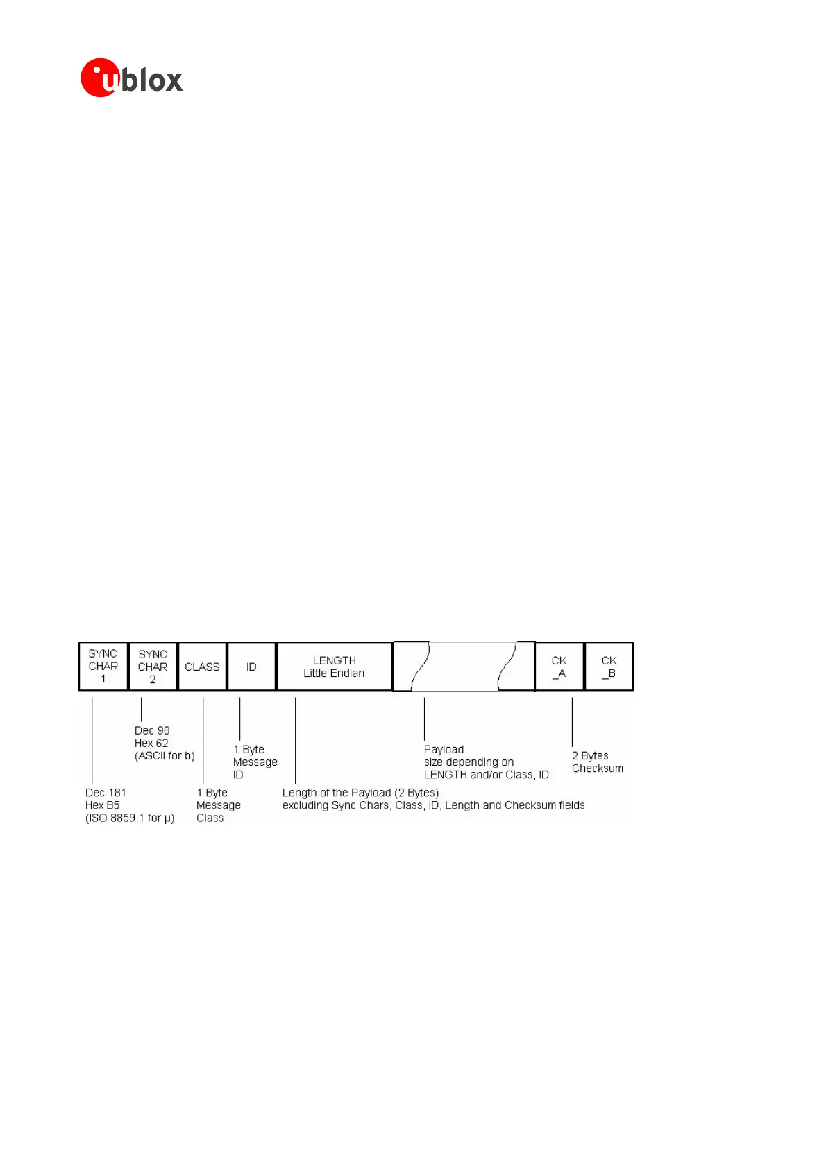
4.4.3.1 UBX Packet Structure
AbasicUBXpacketlooksasfollows:
Note The voltage range for VDDUSB is specified from
specificat
he GPS Receivers a u etary protocol to
protocolhasth
ansmit GPS data t computer
ousRS232orUSB rts. followingkeyfeatu
ct.8Bitbinary
protected,
isu
checksumalgorit
M lar,usinga2-stag
ess (Cla eID)
UBX protocol of
optimized
s a owerful messages than N EA protocol. It’
debugging.
The ANTARIS
®
4 receiver features a
2. Messages
Forfurtherinformationplease
refertoANTARIS
®
4GPS Protocol Specifications [9].
Figure 70: UBX Protocol Framing
• Everymessagestarts
• A1ByteClassFieldfollows.
•
with2Bytes:0xB50x62
TheClassdefinesthebasicsubsetofthemessage
A1ByteIDFielddefinesthemessagethatistofollow
It doesnot
include Sync Chars, Length Field, Class, ID or CRC fields. The number format of the length field is an
unsigned16-BitintegerinLittleEndianFormat.
• ThePayloadisavariablelengthfield.
• CK_AandCK_Bisa16Bitchecksumwhose
calculationisdefinedbelow.
• A 2 Byte LengthField is following. Length is defined as being thelength
of the payload,only.
GPSModules-SystemIntegrationManual(SIM)(incl.ReferenceDesign) ReceiverDescription
GPS.G4-MS4-05007-A1
Page 82
 Loading...

