Moreover,the GPSbandisfarbeyondthe1GHz limitthatappliestoalmostallEMCregulations.So, evenifa
deviceiscompliantwithrespecttoEMCregulationsitmightseverelydisturbaGPSreceiver.
IftheGPSantennaistobeplacedveryclosetosomeotherelectronics,
e.g.theGPSreceiveritselforaPDA-like
e, nvery seriously rightfromthe conceptphaseofthe design.Itis oneof
r and Ground Planes
Usesolidplanesforpowerandgroundinterconnect.ThiswilltypicallyresultinaPCBwithatleastfourlayersbut
willalsoresultinamuchlowerradiation.Solidgroundplanesensurethatthereisadefinedreturnpathfor
the
signals routed on thesignal layer.Thiswill reduce the “antenna” areaof the radiating loop. Planes shouldbe
solidinasensethattherearenoslotsorlargeholesinsidetheplane.
Theouterextentofthepowerplaneshouldbewithintheextentoftheground
plane.Thisavoidsthattheedges
of the two planes form a slot antenna at the board edges. It’s a good idea to have a ground frame on the
circumferenceofeverylayerthatisconnectedtothegroundplanewithasmanyviasaspossible.Ifnecessary,a
shield can
then be easily mounted on top of this frame (see Figure 12). Furthermore, free space on the
outermost Layers can be filled with ground shapes connected to the ground plane to shield radiation from
internallayers.
applianc theEMC issuemust betake
the most demanding tasks in electrical engineering to design a system that is essentially free of measurable
emissionsinagiven
frequencyband.
1.6.2 Eliminating Digital Noise Sources
Digital noise is caused by short rise-times of digital signals. Data and address buses with rise-times in the
nanosecondrangewillemitharmonicsuptoseveralGHz.Thefollowingsectionscontainsomegeneralhintson
howtodecreasethelevelofnoiseemittedfromdigitalcircuitboardthatarepotentiallyin
closeproximitytothe
GPSreceiverortheantenna.
1.6.2.1 Powe
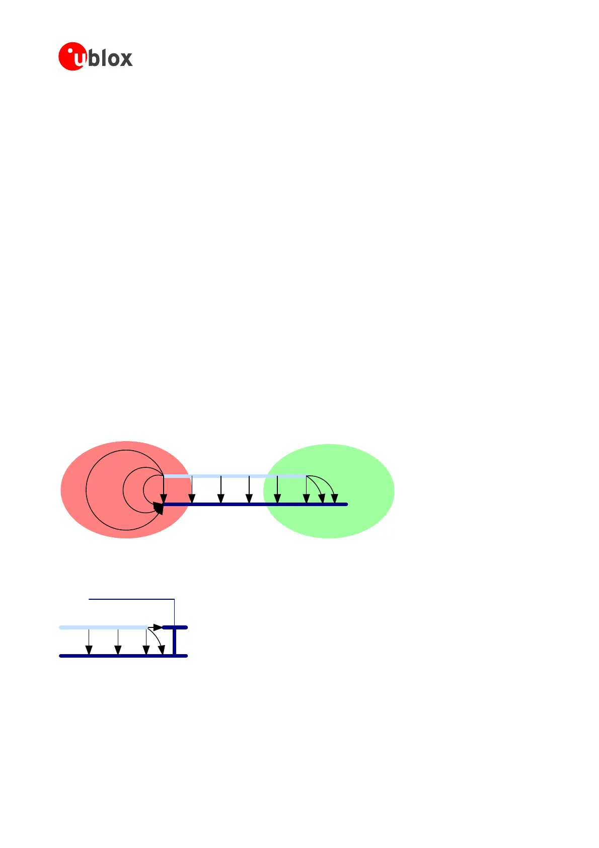
Bad: Excessive Radiation
Good: Radiation terminated
Figure 12: Signal and power plane extends should lie within ground plane extends
Optional shield
Figure 13: Further improvement of reduction of power plane radiation
1.6.2.2 High Speed Signal Lines
Keep high-speed lines as short as possible. This will reduce the area of the noise-emitting antenna, i.e. the
conductor traces. Furthermore, the use of line drivers with controlled signal rise-time is suggested whenever
GPSModules-SystemIntegrationManual(SIM)(incl.ReferenceDesign) GPSFundamentals
GPS.G4-MS4-05007-A1
Page 23
 Loading...

