your position is our focus
Generaldesignrecommendations:
• Thelengthofthemicrostriplineshouldbekeptasshortaspossible.Lengthsover2.5cm(1inch)shouldbe
avoidedonstandardPCBmaterialand additionalshielding.without
• Distance between micro strip line and ground area on the top layer should at least be
as large as the
dielectricthickness.
• RoutingtheRFconnectionclosetodigitalsectionsofthedesignshouldbeavoided.
• Toreducesignalreflections,sharp anglesintheroutingofthemicrostriplineshouldbeavoided.Chamfers
or fillets are preferred for rectangular routing; 45-degree routing is preferred
over Manhattan style
90-degreerouting.
Antenna
16
17
18
19
20
21
22
23
24
25
26
27
28
29
15
14
12
11
10
9
8
7
6
5
4
3
2
1
13
Antenna
16
17
30
18
19
20
21
22
23
24
25
26
27
28
29
15
14
12
11
10
9
8
7
6
5
4
3
2
1
13
Antenna
16
17
18
19
20
21
22
23
24
25
26
27
28
29
15
14
12
11
10
9
8
7
6
5
4
3
2
1
13
30
PCB
30
PCB PCB
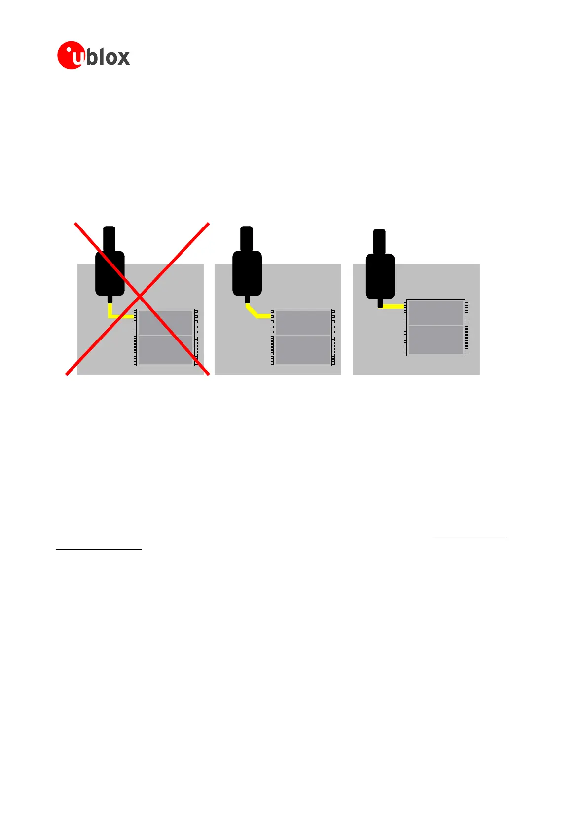
Wrong better best
• RoutingoftheRF-connectionunderneaththe receivershouldbeavoided.Thedistanceofthemicrostripline
tothegroundplaneonthebottomsideofthereceiverisverysmall(some100µm)andhashugetolerances
(upto100%).Therefore,theimpedanceofthis
partofthetracecannotbecontrolled.
• Useasmanyviasaspossibletoconnectthegroundplanes.
• Inordertoavoidreliabilityhazards,theareaonthePCBunderthereceivershouldbeentirelycoveredwith
soldermask.Viasshouldnotbeopen.
3.6.5 Antenna Micro Strip
Therearemanywaystodesignwave-guidesonprintedcircuitboards.Commontoallisthatcalculationofthe
electrical parameters is not straightforward. Freeware tools like AppCAD from Agilent or TXLine from Applied
Wave Research, Inc. are of great help. They can be downloaded from
www.agilent.com and
www.mwoffice.com.
Themicrostripisthemostcommonconfigurationforprintedcircuitboards.Thebasicconfigurationisshownin
Figure 45 and Figure 46.As arule ofthumb, fora FR-4materialthewidthoftheconductorisroughly double
thethicknessofthedielectrictoachieve50Ohmslineimpedance.
to consider the distance
and theadjacent GND
eonthesamelayer
UsetheCoplanarWaveguidemodelforthecalculation
ofthemicrostrip.
For
the correct calculation of the micro strip impedance, one does not only need
betweenthe topand thefirstinnerlayerbutalso thedistance betweenthe microstrip
plan
Note:
GPSModules-SystemIntegrationManual(SIM)(incl.ReferenceDesign) Design-In
GPS.G4-MS4-05007-A1
Page 56
 Loading...

