your position is our focus
3 sign
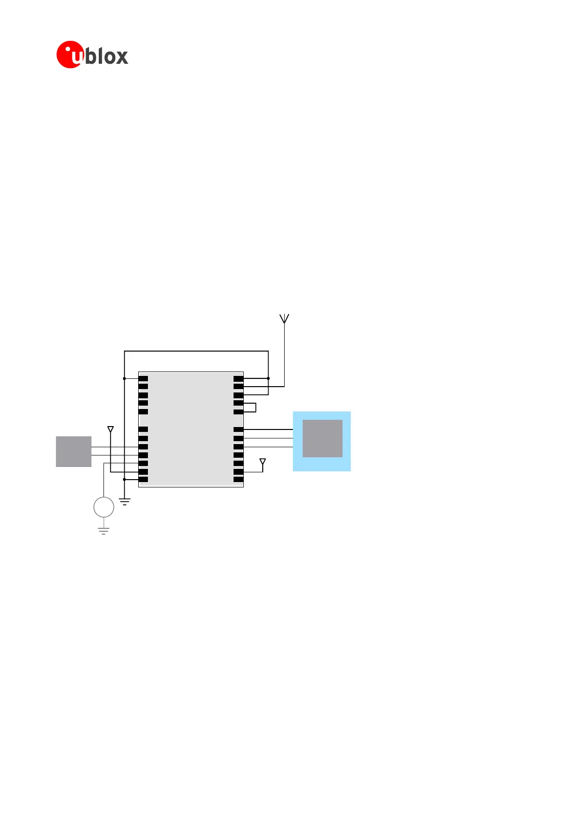
F esign N efollowin andpinshavetobeconsidered:
• ConnectthePowersupplytoVCC.
• Assureaoptimalgroundconnectiontoallg
• ConnecttheantennatoRF_INoveramatch
• Ifanactiveantennashallbeconnected
toNEO,m addaninductorfortheantennabiasvoltage
as sectio 4.3.3.1 the
• Connectpins8and9together.
• If dHot-o Wa li T
• Decide
whetherthe TIMEPULSEoption isr riatepinson
yo le
This is mal setu for GPS receiver n
r uir Table .
.4 NEO-4S De
ora minimalD with EO-4S,th gfunction
roundpins
ing50Ohmmicrostrip.
akesureto
shownin n andfollow layoutrecommendationsinsection3.6.6.
younee r rmstartinyourapp cation,connectaBackupBatterytoV_BA
equiredinyour applicationandconnect theapprop
urmodu
a mini p a PVT with NEO-4S. Now check about special functions and desig
eq ementsin 7
Vcc
Micro
Processor
(serial)
Passive Antenna
NEO-4S
Backup
Battery
+
NEO-4S
1
2
3
4
5
6
7
8
9
10
11
12
24
22
21
20
19
18
17
16
15
14
13
23
GND BOOT_INT
SELECT
TIMEPULSE
EXTINT0
USB_DM
USB_DP
VDDUSB
(Reserved)
VCC_RF
GND
GND
RF_IN
VCC
T
RxD1
TxD1
(Reserved)
(Reserved)
S
/CFG
SO
SI
GND
V_BA
NC
SCK
MI
_USB
MO
Vcc
Micro
SB port (optional)
F e Antenna Des or NEO-4S Receive
Processor
(USB)
U
igur 39: Passive ign f rs
GPSModules-SystemIntegrationManual(SIM)(incl.ReferenceDesign) Design-In
GPS.G4-MS4-05007-A1
Page 49
 Loading...

