your position is our focus
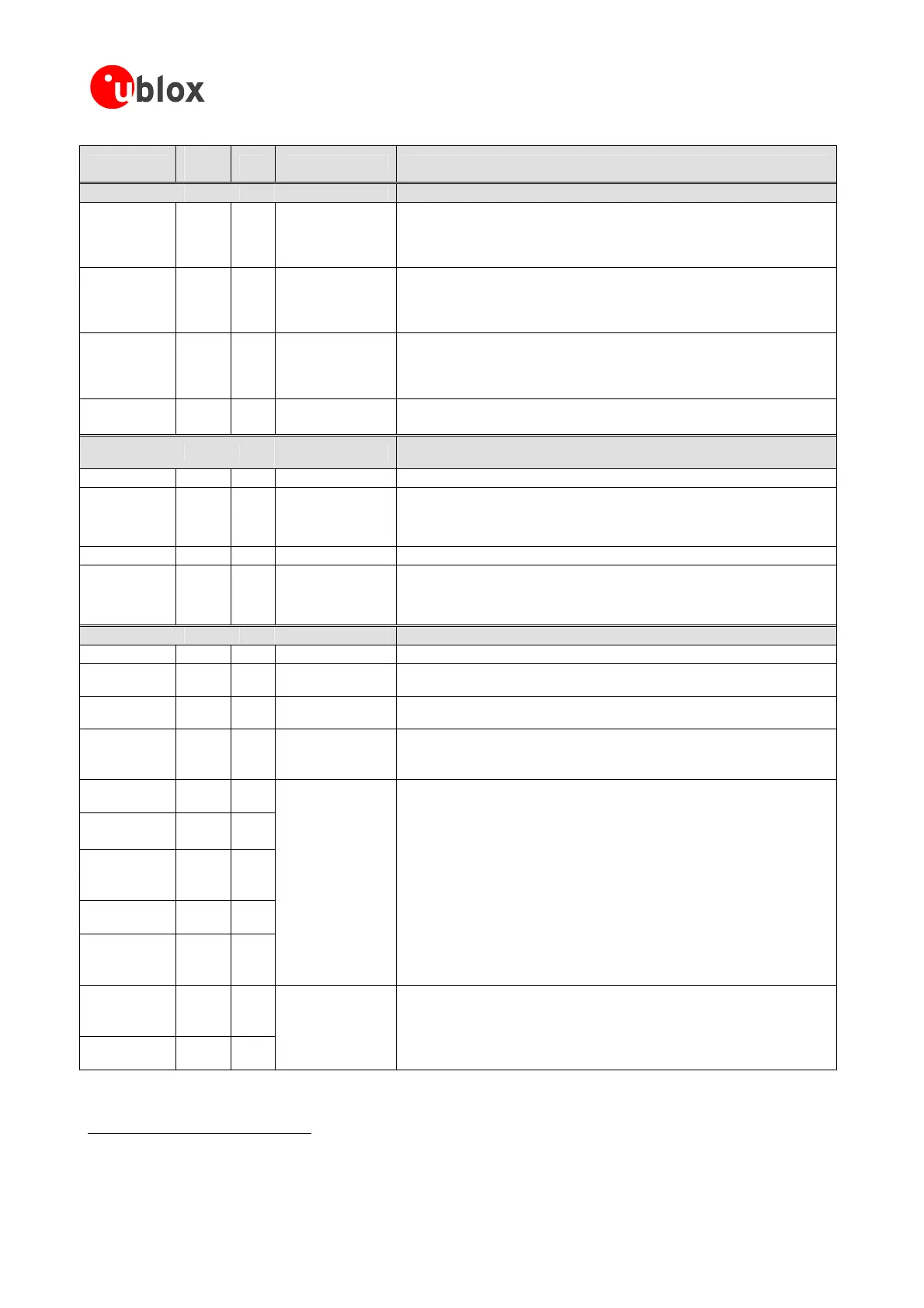
Function
PIN
(TIM)
I/O Description Remarks
Antenna
RF_IN
17 I
fromantenna
connector(fordet
GPSsignalinput
TheconnectiontotheantennahastoberoutedonthePCB.Use acontrolled
impedanceof50OhmtoconnectRF_INtotheantennaortheantenna
ailsrefertoSection 3.6.5)
UseV_ANTpintosupplypower.Don’tsupplyDCthroughthispin.
ConnecttoGNDifPassiveAnten
V_ANT
19 I
AntennaBias
voltage
IfanactiveAntennaisused,adda10Rresistor(see 4.3.3.2)infrontofV_ANT
inputtotheAntennaBiasVoltageorVCC_RFforshort
theantennasupervisorcircuitry(see 4.3.3.2).
naisused.
circuitprotectionoruse
VC _RF
20 O
OutputVoltageRF
V_ANT).ThemaxpowerconsumptionoftheAntenna
datasheetspecificationofthemodule(seealso4.3.3).
C
Canbeusedtopoweranexternalactiveantenna(VCC_RFconnectedto
mustnotexceedthe
section
Leaveopenifnotused.
AADET_N
27 I
Detect
Leaveopenifnotused.
ActiveAntenna
Signalpinforoptionalantennasupervisorcircuitry(see 4.3.3.2).
Serial Port
Theserialinterfaceis3VCMOSand5VTTLcompatible.Forothervoltagelevels
usetheappropriatelevelshifters.
TxD1
5 O SerialPort1
3V
RxD1
4 I SerialPort1
5Vtolerantserialportinput.Internalpull-up resistorto V_BAT.Leaveopenif
notused.
Note Don’tuse anexternalpullupresistor.
TxD2
6 O SerialPort2
3V
RxD2
7 I SerialPort2
5Vtolerantserialportinput.Internalpull-up resistorto V_BAT.Leaveopenif
notused.
Note Don’tuse anexternalpullupresistor.
System
BOOT_INT
3 I Bootmode
DonotconnectonTIM-4AandTIM-4Sreceivers.
RESET_N
22 I
HardwareReset
(ActiveLow)
Leaveopenifnotused.Donotdrivehigh.SeealsoSection 4.9.2.
TIMEPULSE
29 O TimepulseSignal
ConfigurableTimepulsesignal(onepulsepersecondbydefault).Leaveopenif
notused.SeealsoSection 4.7.1.
EXTINT0
23 I ExternalInterrupt
ExternalInterruptPintowakeupreceiverinFixNOW™sleepmode.Seealso
Section 4.2.7.1and4.9.4forfurtherinformation.
Internalpull-upresistorto V_BAT
5
.Leaveopenifnotused.
GPSMODE2
6
/
PCS1_N/ P27
24 I/O
GPSMODE5/
SCK1/ P17
8 I/O
GPSMODE6/
SS_N/ P26
PCS0_N/
25 I/O
GPSMODE12/
30 I/O
PCS3_N/ P29
GPSMODE3/
EXTINT1/
P13/
9 I/O
GPSMODEPin
TIM-4A/ TIM-4S:
GPSMODEPin;leaveopenifdefaultconfigurationisused.
RefertoSection4.8.2forfur rinformation.
TIM-4H / TIM-4P:
GPIOPin;leaveopenifnotused.
TheGeneralPurposeI/O(GPIO)canonlybeprogrammedwiththeANTARIS
®
4
SoftwareCustomizationKit,pleaserefertotheSCK Manual [8]whenintending
touseoftheGPIO’softhereceiver.
GPIO/
the
NU / SCK/
P23
26 I/O
NU/ MOSI/
P24/
28 I/O
GPIO/NC
TIM-4A/ TIM-4S:
Notconnected;leaveopen.
TIM-4H / TIM-4P:
GPIOPin;leaveopenifnotused
Table 6: Pin-out TIM-4x
5
DonotpullupasitmayincreaseyourBatteryBackupCurrent.
6
PulltoGNDtoachieveNormalSensitivityModesettingatstartup.
GPSModules-SystemIntegrationManual(SIM)(incl.ReferenceDesign) Design-In
GPS.G4-MS4-05007-A1
Page 48
 Loading...

