your position is our focus
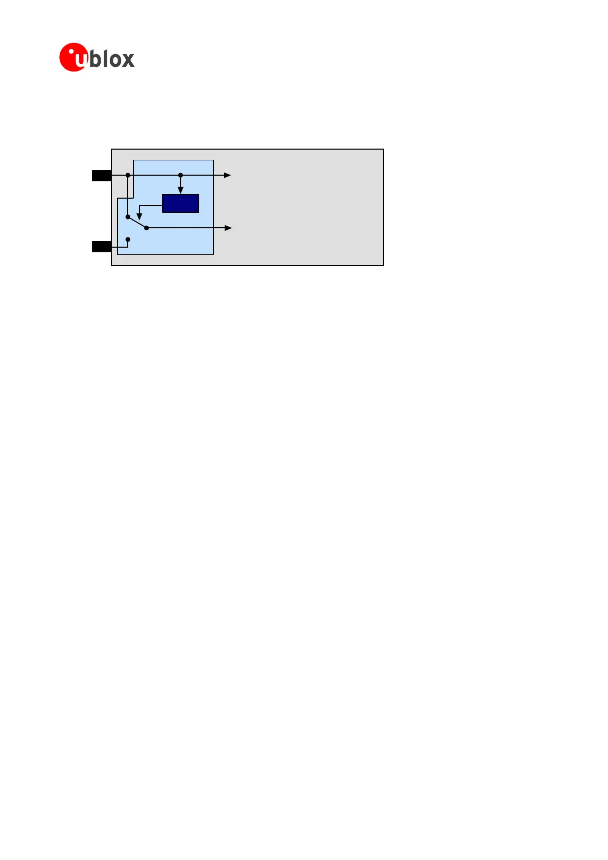
Aslong asVccissuppliedtotheANTARIS
®
4GPSReceiver,thebackupbatteryisdisconnectedfromtheRTCand
thebackupRAMinordertoavoidunnecessarybatterydrain(seeFigure 52).PowertoRTCandBBRissupplied
fromVccinthiscase.
VCC
VBAT
Voltage
Supervisor
GPS Voltage Supply
RTC and Battery Backup RAM (BBR)
J1
Figure 52: Backup Battery and Voltage
BeforeVccissuppliedforthefirsttime,switchJ1Figure 52isnotinitialized.Inthiscaseincreasedbatterydrain
ightoccurifthebackupbatteryisconnectedtotheV_Batpin.Thebatterydrainwilldroptothespecifiedlevel
a thefirsttime.
N toconnectthebackupbatter –powerupthemodule
forashorttime(e.g.1s)ASAPafterconn eryinordertoavoidexcessivebattery
4 d current in low
S pins RxD1, to
wakeupfromFixNOWsleepmodes.For thatreason venifVCCis
t e internal pull-up
µA) flows through these internal
r .Toavoidthiscurren anorder
o bilities:
•
• ereceiverisinsle
• ichdrivethesepins, epor
backupmode.
N edoff,acurrent tterythroughthepull-up resistors
XTINT0 a r circuit
r).
m
ssoonasVccisapplied
ote It’sadvised ywhileVccisonor–ifnotpossible
ectingthebackupbatt
drain.
.2.3 Avoiding increase power modes
pecial attention has to be paid to the RxD2, EXTINT0 and EXTINT1. These 4 pins can be used
thesepinsarepoweredfrombackupsupply,e
urned off. Since these pins hav resistors, current
(e.g. 15
esistorsifthepinisdrivenlow t,whichincreasesthesleeporbackupcurrentsby
fmagnitude,therearedifferentpossi
Leavethesepinsopen.
Pullthemtoa“HIGH”whileth epor
backupmode
Makesuretheoutputs,wh areinhigh-impedancestatewhilethereceiverisinsle
ote Whenthesystemisturn mayflowfrombackupba
of these 4 pins (RxD1, RxD2, E nd EXTINT1) through ESD protection diodes of you
(i.e.micro-controlle
GPSModules-SystemIntegrationManual(SIM)(incl.ReferenceDesign) ReceiverDescription
GPS.G4-MS4-05007-A1
Page 62
 Loading...

