GPSModules-SystemIntegrationManual(SIM)(incl.ReferenceDesign) Design-In
GPS.G4-MS4-05007-A1
Page 53
your position is our focus
3.6.2 Paste Mask
Module
0.8mm
[32m il]
a
a
Cu mask
Solder mask
Paste mask
minimal
distanceto
next
componen t
See
Enlargement
b
0.8mm
[32m il]
d
a
Solder Paste
e
c
Cu Pad
0.8mm[3 2 m il]
C
u
Ma
s
k
Module
0.65mm
[
2 6 m il]
Cu Mask
Cu
Ma
s
k
b
0.1mm
[4mil]
0.2mm
[7 8 m il]
0.15mm
[5 9 m il]
SolderPaste:crosssection
ENLARGEMENT
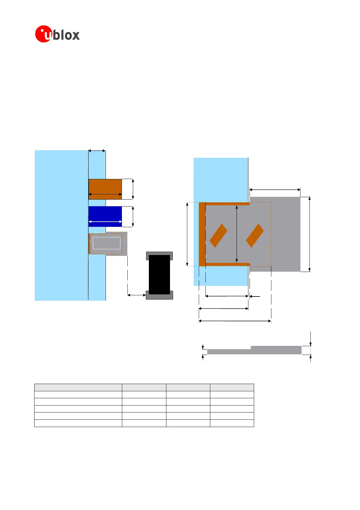
Figure41andTable8demonstratetherecommendedpositioningofCu,SolderandPasteMasks,aswellasthe
suggested distances. Note that these are recommendations only and not specifications. The exact geometry,
distancesandsolderpastevolumesmustbeadaptedtothespecificproductionprocesses(e.g.solderingetc.)of
e mask under the
moduleandtoincreasetheamountofpastemaskoutsidethemodulebyusingastepstencilandexceedingthe
pastemask beyond theCu Mask asshown in
Figure41.If astepstencil isnotused itis stillrecommended to
employthesamevolumeofsolderpasteoutsidethemoduletoattainthedesiredlevelofwetting.Thiswillhave
tobedonebymodifyingtheshapeofthepastemaskoutsidethemodule.
Figure 41: Solder and paste mask with enlargement showing positioning and cross section of underlying solder paste
the
customer.
To improve the wetting of the half vias it is recommended to reduce the amount of past
Dimension TIM-4x LEA-4x
NEO-4S
a 1.8mm[70mil] 1.8mm[70mil] 1.7mm[66mil]
b 1.0mm[39mil] 1.0mm[39mil] 0.9mm[35mil]
c 0.65mm[26mil] 0.65mm[26mil] 0.65mm[26mil]
d 0.9mm[35mil] 0.8mm[32mil] 0.8mm[32mil]
e 1.3mm[51mil] 1.5mm[59mil] 1.5mm[59mil]
Table 8: Paste Mask Dimensions for TIM-4x, LEA-4x and NEO-4S
Note The exact geometry, distances, stencil thicknesses, step heights and solder paste volumes must be
adaptedtothespecificproductionprocesses(e.g.solderingetc.)ofthecustomer.
 Loading...

