1.6.3.2 Shielding Sets of Sub-System Assembly
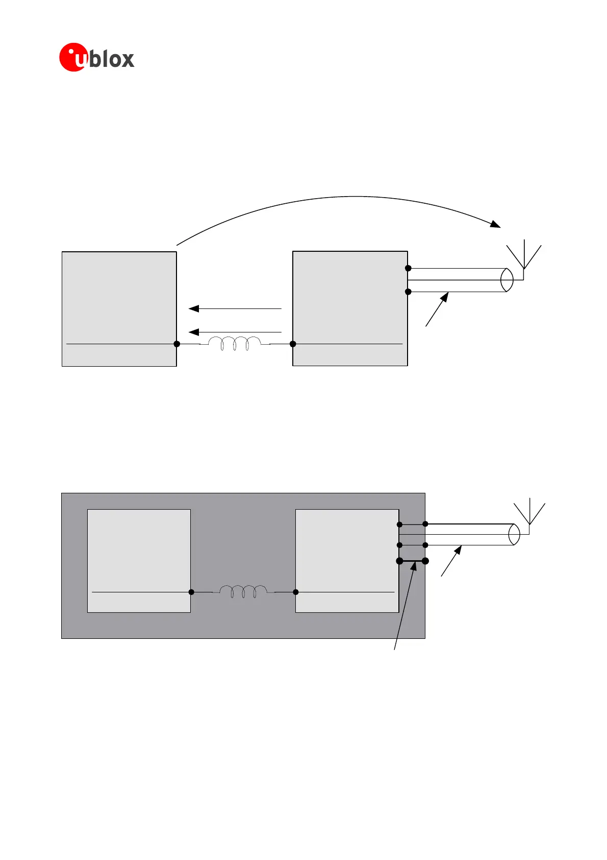
Yet another problem arises if multiple building blocks are combined in a single system. Figure 21 shows a
possiblescenario.Inthiscase,thesupplycurrenttravelingthroughtheinductivegroundconnectionbetweenthe
two sub-systems will cause a voltage difference between the two shields of the sub-system. The shield of
the
othersystemwillthenactasatransmittingantenna,radiatingwithrespecttothegroundandshieldoftheGPS
receiverandtheattachedantenna.
SomeotherElectronics
GPSReceiver
Antenna
RadiationfromShield
Ground
Connection
ReturnC urrent
VoltageDifference
Coaxialantennacable
Figure 21: Two shielded sub-systems, connected by a “poor” ground
This situation can be avoided by ensuring a low inductivity ground connection between the two shields. But
now,itmightbedifficulttocontrolthepathofthegroundreturncurrentstothepowersupplysincetheshield
isprobablyconnectedtothesupplygroundatmorethanonelocation.The
preferredsolutionisshowninFigure
22.Again,itisimportanttohaveagood(i.e.lowinductance)interconnectionbetweentheoutershieldandthe
shieldinggroundoftheGPSreceiver.
SomeotherElectronics GPSRec eiv er
PowerSupplyGround
Connection
Antenna
Connectionofshieldinggrounds
Coaxialantennacable
m assembly
Asalreadypointedout,inasetuplikethisitisimportanttokeeptheshield
freefrom
supplycurrentswith highfrequency spectralcontent. Ifthere aretobeadditionalconnectionsto theshielding
ground,theseshouldbeofahighlyinductivenature.
Figure 22: Proper shielding of a sub-syste
It is clear that the situation illustrated in Figure 22 can become complex if the component “Some other
electronics” contains another wireless transmitter system with a second antenna, which is referenced to the
systemsshieldingground.
GPSModules-SystemIntegrationManual(SIM)(incl.ReferenceDesign) GPSFundamentals
GPS.G4-MS4-05007-A1
Page 28
 Loading...

