EasyManua.ls Logo

uAvionix AV-30-E - User Manual

uAvionix AV-30-E
139 pages
Print Icon
To Next Page IconTo Next Page
Loading...
UAV-1004234-001
Rev H
AV-30-E
Installation Manual

Table of Contents

Other manuals for uAvionix AV-30-E

Questions and Answers

  • D
    Daniel CunninghamSep 12, 2025
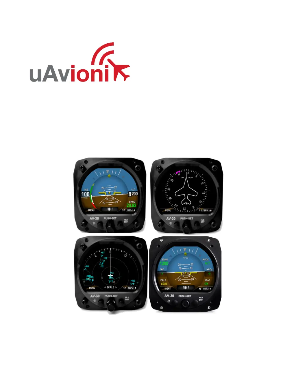
    How to stop nuisance alerts on uAvionix Avionics Display?
    • A
      awashingtonSep 12, 2025
      If the uAvionix Avionics Display is generating nuisance alerts, ensure the alerting limits are configured as desired in the Setup menu.
  • R
    Reginald HendersonSep 9, 2025
    What to do if uAvionix AV-30-E flashes “NO MAG”?
    • J
      Jennifer PageSep 9, 2025
      If the uAvionix Avionics Display flashes “NO MAG” on the right side, check that you have selected the intended internal or AV-Mag external magnetometer function. Also, check the AV-Mag wiring for intermittent connection or poor grounding.
  • C
    Christopher BaxterSep 8, 2025
    What to do if uAvionix AV-30-E Avionics Display shows “NO DATA”?
    • A
      Ashley ReynoldsSep 8, 2025
      If the uAvionix Avionics Display shows “NO DATA”, check the interface cables and pinouts.
  • S
    Steven TownsendSep 7, 2025
    How to fix uAvionix AV-30-E Avionics Display if it does not power on?
    • M
      Matthew RodriguezSep 7, 2025
      If the uAvionix Avionics Display does not power on, check the associated breakers. Also, ensure the aircraft battery is greater than 10 VDC and check the wiring and pinouts.
  • R
    riceruthAug 23, 2025
    What to do if the uAvionix AV-30-E Avionics Display shows “NO AP” flag when selecting an autopilot mode?
    • T
      Tracy LiAug 23, 2025
      If the uAvionix Avionics Display shows “NO AP” when selecting an autopilot mode or while the AP is active, this means that the AV-30-E is either not communicating with the AV-APA, or that the AV-30-E does not have the information needed to perform the mode selected. If using an autopilot mode that uses GPS, make sure that the GPS has signal and an active flight plan.
  • B
    bradleytannerSep 5, 2025
    How to correct small but constant error in Roll, Pitch or Slip on uAvionix Avionics Display?
    • C
      Clifford WattsSep 5, 2025
      To correct a small but constant error in Roll, Pitch, or Slip on your uAvionix Avionics Display: 1. Ensure the unit is level in the panel using a bubble level or similar. 2. Set the trim adjustment in the Installation menu. See the Installation Manual for instructions.
  • M
    monica67Sep 4, 2025
    How to correct small but constant error in airspeed or altitude on uAvionix AV-30-E Avionics Display?
    • J
      Jordan MontgomerySep 4, 2025
      To correct a small but constant error in airspeed or altitude on your uAvionix Avionics Display, set the trim adjustment in the Installation menu. See the Installation Manual for instructions.
  • K
    Kristina ThomasSep 3, 2025
    What to do if GPS information is expected but does not show up in data overlays of uAvionix AV-30-E?
    • J
      Joshua MirandaSep 3, 2025
      If GPS information is expected but does not show up in data overlays on your uAvionix Avionics Display, check if the GPS input is configured to match the connected GPS serial data type and speed. Also, set the direction indication to GPS TRK.
  • R
    Renee FigueroaSep 1, 2025
    Why does uAvionix Avionics Display generate nuisance alerts?
    • S
      Stephanie SantosSep 2, 2025
      If your uAvionix Avionics Display generates nuisance alerts, ensure alerting limits are configured as desired in the Setup menu.
  • J
    Julia SmallSep 1, 2025
    What to do if my uAvionix AV-30-E Avionics Display will not shut off?
    • E
      eric66Sep 1, 2025
      If your uAvionix Avionics Display will not shut off, even if power is removed, ensure no pitot or static blockage or line kinks are present, which could be locking pressure and airspeed indication over 40 knots.

Summary

1 Revision History

2 Warnings; Disclaimers

3 Limited Warranty

5 Introduction

5.1 Purpose

This installation manual applies to the AV-30-E (non-certified) and other product variants.

5.2 Definition of Acronyms & Terms

Provides definitions for acronyms and terms used throughout the AV-30-E installation manual.

6 AV-30 System Information

6.1 System Description

Details the uAvionix AV-30 as a digital multi-mode instrument for aircraft cockpits.

6.2 System Functions

Outlines the primary, supplemental, and audio/visual alerting functions of the AV-30 system.

7 Design Standards

7.1 Applicable Performance Standards

Lists the design standards and MOPS the AV-30 satisfies for performance.

8 Installation Locations & Operating Modes

8.1 Installation Locations

Shows typical six-pack instrument arrangement and AV-30 placement.

8.2 Operating Mode Configuration

Explains how to set the AV-30's operating mode (AI, DG, MFD) during installation.

9 Functionality and Required Interfaces

9.1 Aircraft Systems Connections

Details the electrical and pneumatic connections required for AV-30 system integration.

9.2 Feature Matrix

Tabulates features supported by the AV-30 in AI and DG modes and their required interfaces.

9.2.3 Outside Air Temp Input (Optional)

Describes the optional connection for an Outside Air Temperature (OAT) probe.

9.2.4 Audio Output (Optional)

Details the optional audio panel connection for low-voltage analog output.

9.2.5 Navigation Interface (Optional)

Covers the optional RS-232 serial interface for connecting GPS units or AV-HSI.

9.2.6 Internal Magnetometer (Optional)

Describes the optional internal magnetometer and its calibration requirements.

9.2.1 AV-Mag External Magnetometer (Optional)

Details the optional AV-Mag external magnetometer, its sensitivity, and calibration needs.

9.2.2 Transponder Control (Optional)

Explains how the AV-30 can control uAvionix transponders like BeaconX.

9.2.3 AV-Link Interface (Optional)

Covers the AV-Link accessory for traffic display via Wi-Fi with ADS-B receivers.

9.2.4 Autopilot Interfaces (Optional)

Details AV-30's capability to control analog and digital autopilots, often via AV-APA.

9.3 Internal Battery Operation

Explains the AV-30's internal battery, its capacity, and behavior during power loss.

10 Equipment Installation

10.1 Overview

Outlines the general steps involved in installing the AV-30 unit and related components.

10.2 Supplied Components

Lists the components included in the AV-30-E Installation Kit and the AV-30-E units.

10.3 Non-Supplied Components

Lists components that are not supplied with the AV-30-E installation kit but are required.

10.4 Installation Records

Specifies what information needs to be recorded in the aircraft's logbook after installation.

10.5 Mechanical Drawing

Provides dimensional drawings of the AV-30 unit for installation planning.

10.6 Mounting the AV-30

Details the procedure for physically mounting the AV-30 unit to the aircraft instrument panel.

10.7 Wiring Diagrams

Explains how wiring varies based on installation configuration and refers to figures for diagrams.

10.8 Bonding Requirements

Details the grounding requirements for electrical connections, including shield and strap use.

10.9 Unit Pinout

Provides a table detailing the function of each pin on the AV-30 connector.

11 Optional Equipment Installation

11.1 AV-Link

Details the AV-Link accessory for traffic display, firmware updates, and connectivity.

11.2 Transponder (tailBeaconX)

Introduces the tailBeaconX transponder and its integration with the AV-30.

11.3 AV-Mag External Magnetometer

Details the AV-Mag external magnetometer for heading measurement and installation.

11.4 AV-APA Analog Port Adapter

Introduces the AV-APA for emulating analog heading signals for legacy autopilots.

11.5 Digital Autopilots

Details operation and control of AeroCruze/TruTrak and Trio Pro Pilot autopilots with the AV-30.

11.6 AV-HSI Horizontal Situation Indicator

Introduces the AV-HSI for course and glideslope guidance, and its role as a hub for navigation data.

11.7 Electronic Flight Instrument System (EFIS)

Explains AV-30's role as a backup to EFIS and user variable synchronization.

12 Setup & Configuration

12.1 Startup and Common Controls

Describes the initial splash screen and common user interface controls for AI and DG modes.

12.2 Available Menus

Categorizes menus into Edit Fields, Setup, and Install menus for configuration and setup.

13 Installation Menu

13.1 Mandatory Settings

Covers essential settings required for every AV-30 installation, like Unit Function and Function Lock.

13.2 System Checkout

Details procedures for system checkout before returning the aircraft to service.

14 Troubleshooting

15 Serial Interface Specification

16 Field Update Capability

17 Appendix A: Example Wiring Schematics

uAvionix AV-30-E Specifications

General IconGeneral
BranduAvionix
ModelAV-30-E
CategoryAvionics Display
LanguageEnglish

Related product manuals