APX 525/625 Generator Revision C Pre-Installation
©
2005 Del Medical Imaging Corporation
7/5/2005 Page 59
Note
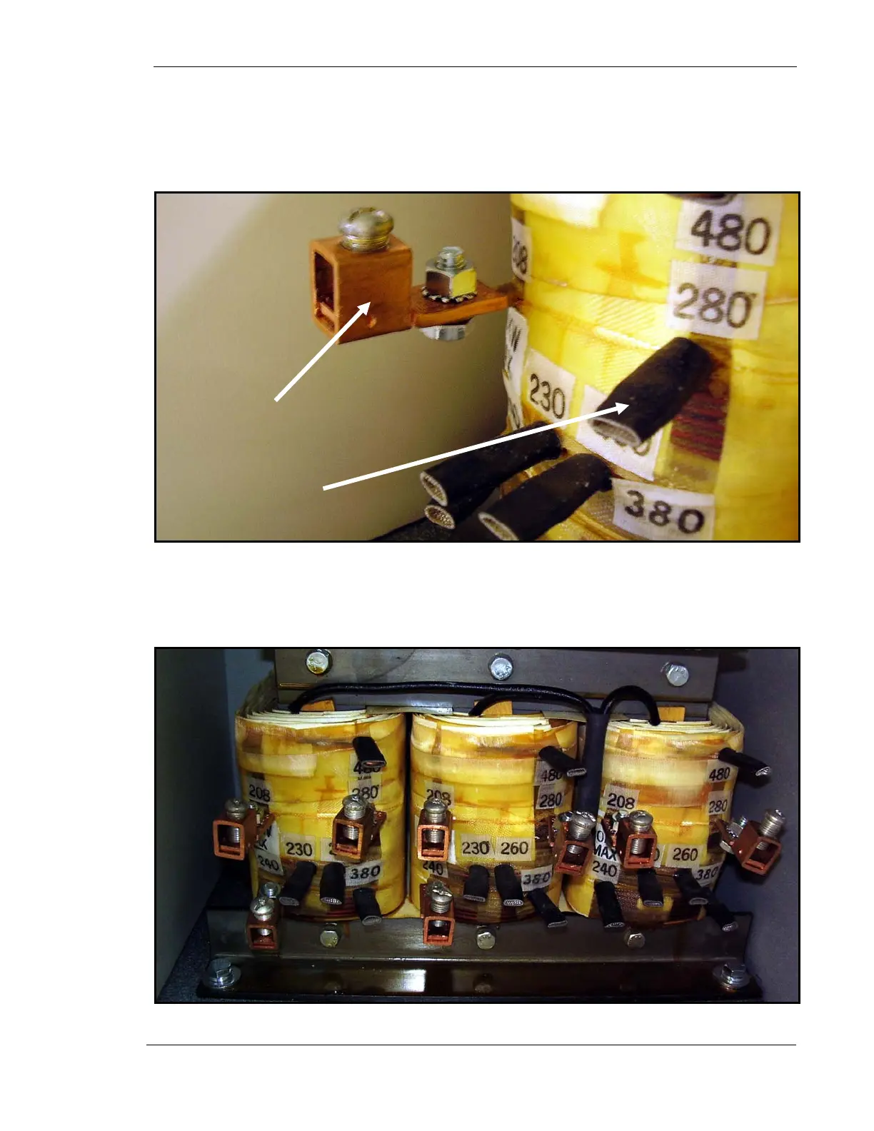
In the following steps, you have to remove select insulators (1 in Fig. 4) and
connect Burndy connectors (2) to select tabs of the in-line transformer. Make
sure that each Burndy connector is connected to each tab exactly as shown in
Figure 4.
Figure 4. Proper Burndy Connection
8. Remove insulators from all 208 & 280 VAC tabs and two left 240 tabs.
9. Connect Burndy connectors to all 208 & 280 VAC tabs and two left 240 tabs
as shown in Figure 5.
Figure 5. Burndy Connections for 208 VAC Hookup
1
T
ical
2
T
ical