APX 525/625 Generator Revision C Pre-Installation
©
2005 Del Medical Imaging Corporation
7/5/2005 Page 80
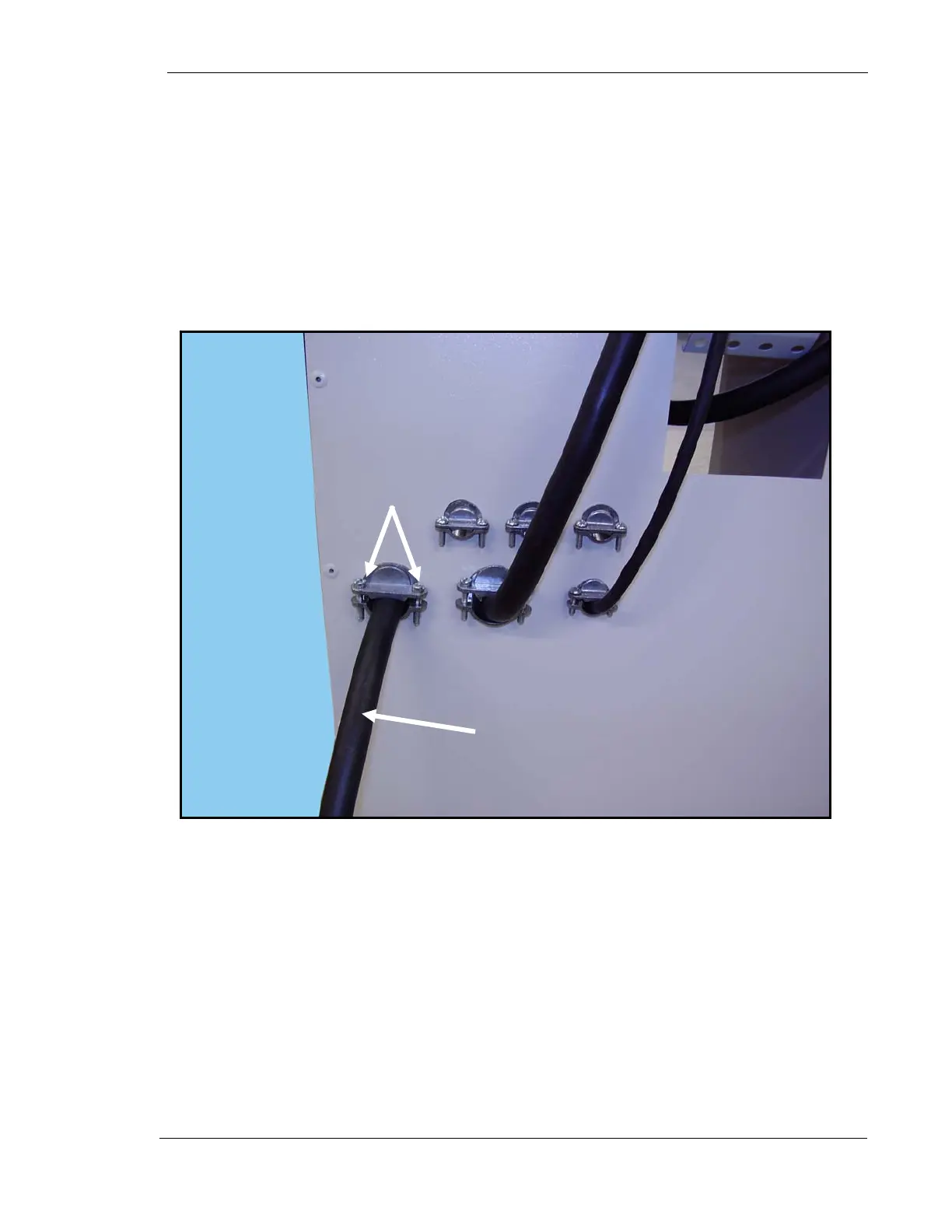
36. Loosen two stress relief clamp screws (1 Fig. 14).
37. Insert the end of the main power cable into the stress relief clamp and into
the generator cabinet until there is enough wire slack inside the cabinet for
the cable wires to reach all tabs on the transformer. The outer insulation on
the cable should be stripped back to allow 12” (30cm) of internal wire
exposed. Each internal wire should have about ½” (10mm) of insulation
stripped from each end.
38. Tighten stress relief clamp screws.
Figure 14. Main Power Cable Stress Relief
2
1