APX 525/625 Generator Revision C Pre-Installation
©
2005 Del Medical Imaging Corporation
7/5/2005 Page 85
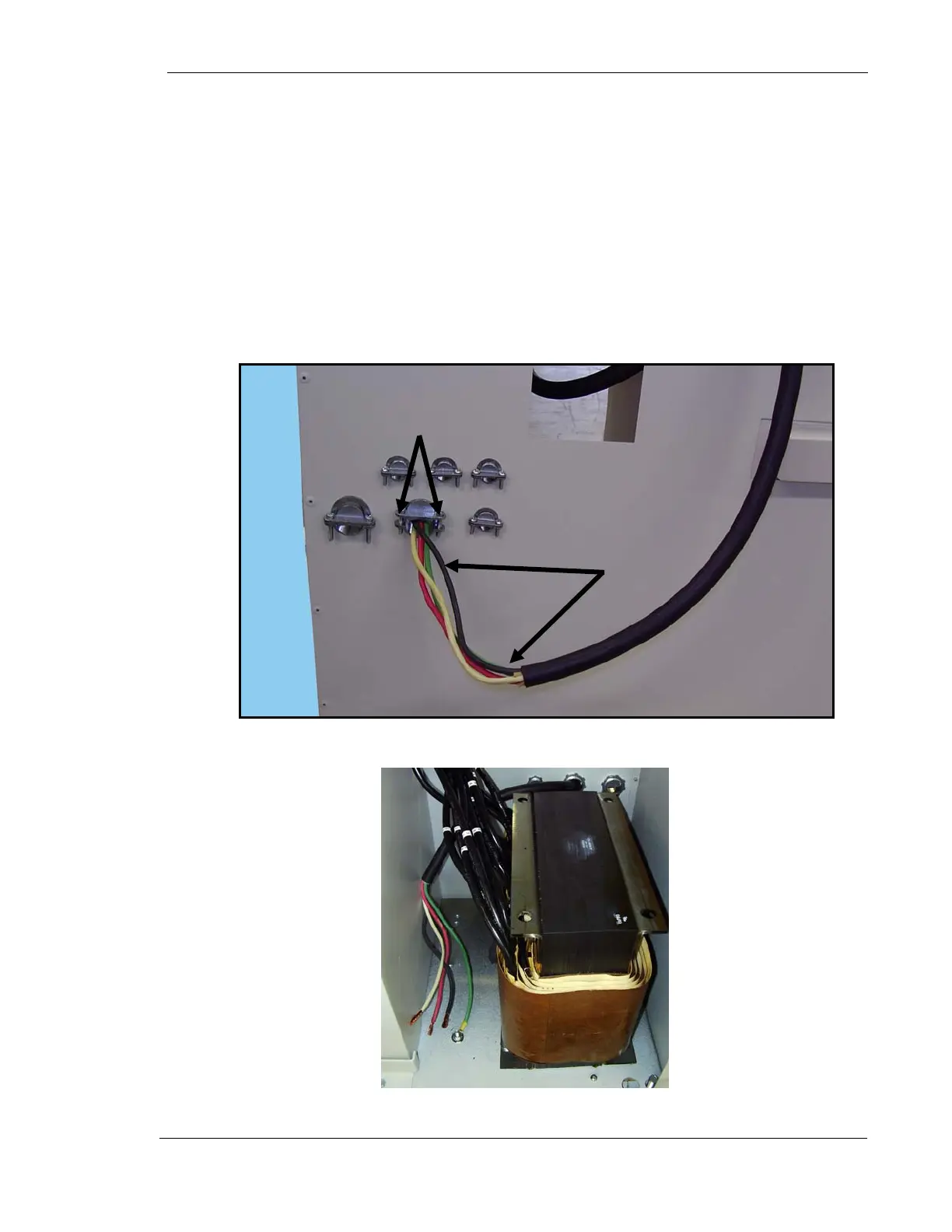
5. Remove main cable (P/N 126-0208G1) from in-line transformer kit. This cable
has four wires. Note that the wires on one end of the cable are longer than
the other end.
6. Loosen two stress relief clamp screws (1 Fig. 5).
7. Insert the end of the cable with the longer wires (2) into the stress relief
clamp and into the generator cabinet until there is enough wire slack inside
the cabinet for the cable’s ground wire to reach the ground stud on the
cabinet’s floor as shown in Figure 5.
8. Tighten stress relief clamp screws.
Figure 5. Main Cable Insertion
Figure 6. Ground Stud
1
2
Ground
Stud