APX 525/625 Generator Revision C Pre-Installation
©
2005 Del Medical Imaging Corporation
7/5/2005 Page 90
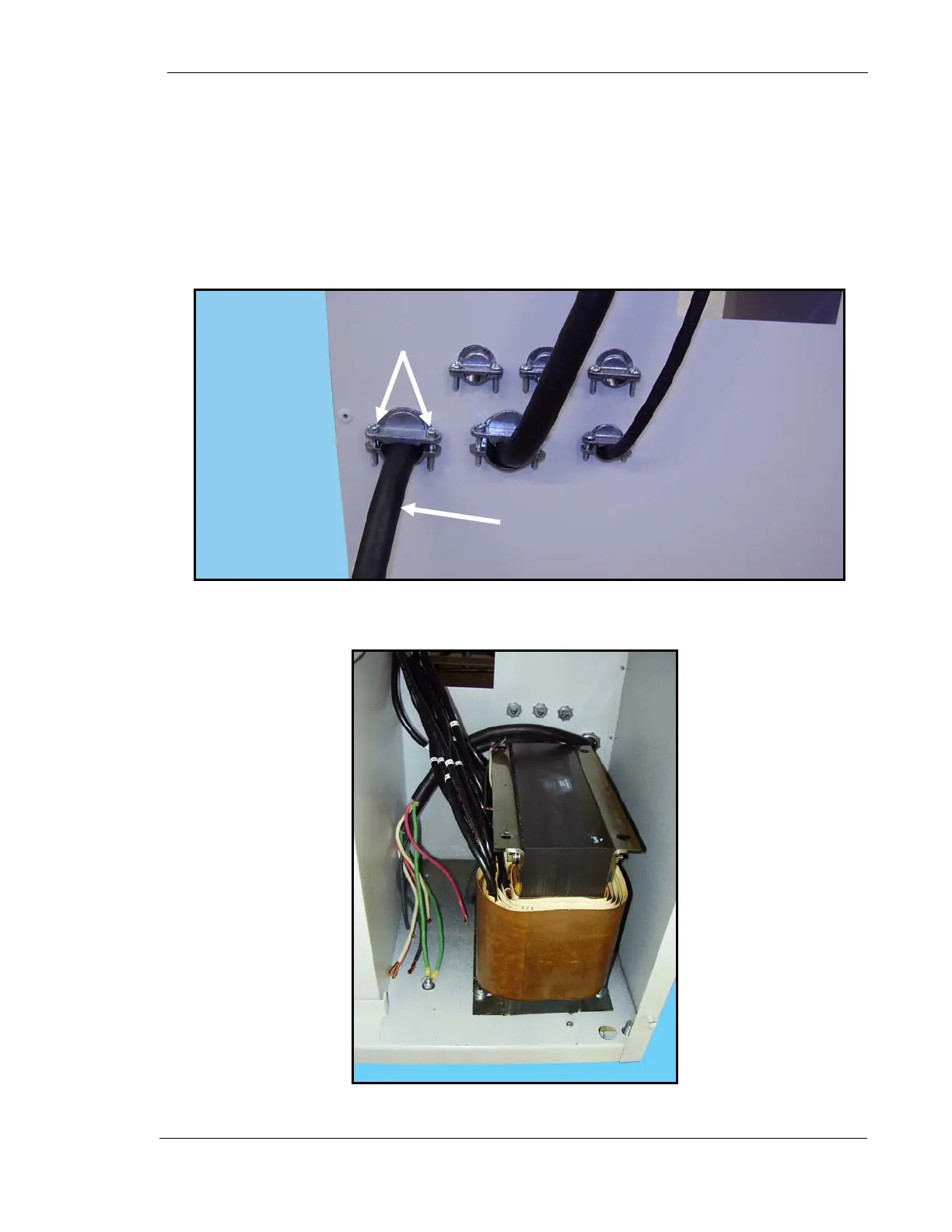
27. Loosen two stress relief clamp screws (1 Fig. 13).
28. Insert the end of the main power cable (2) into the stress relief clamp and
into the generator cabinet until there is enough wire slack inside the cabinet
for the cable’s ground wire to reach the ground stud on the cabinet’s floor as
shown in Figure 14.
29. Tighten stress relief clamp screws.
Figure 13. Main Power Cable Stress Relief
Figure 14. Ground Stud
2
1
Ground
Stud