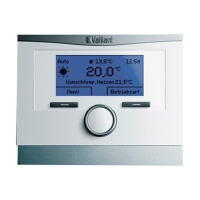
multiMATIC 700/2
Notes
10/2015 86 Training 0020228700_00
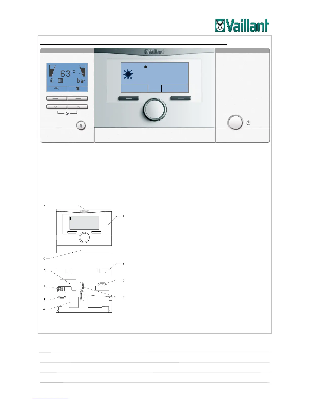
Integrating multiMATIC 700/2 into the current unit electronics box:
Schematic diagram showing the built-in multiMATIC 700/2 controller
On electronics boxes with vertical plug-in connections and five pins, the blanking cover
is removed and then, once the three-pin header has been removed from the controller,
the controller is carefully plugged into the slot provided.
5.1.2 Wall-mounting the controller
Before the controller can be installed in the living
area, it must be separated from the wall-mounting
base. The wall-mounting base is then fitted to the
wall.
After installing the wall-mounting base, the eBUS
line must be connected to the two terminals on the
pin header (5).
Key
5 Controller
6 Wall-mounting base
7 Mounting openings
8 Openings for cable duct
9 Pin header with terminals for the eBUS line
10 Wall-mounting base strip
11 Slot for screwdriver
Desired heating temp. 23.0 °C