multiMATIC 700/2
Notes
10/2015 87 Training 0020228700_00
5.1.3 Installing and connecting the VR 70 module
The VR 70 accessory may be required depending on the design of the heating installa-
tion. It is installed close to the components in the installation using the fastening mate-
rial provided.
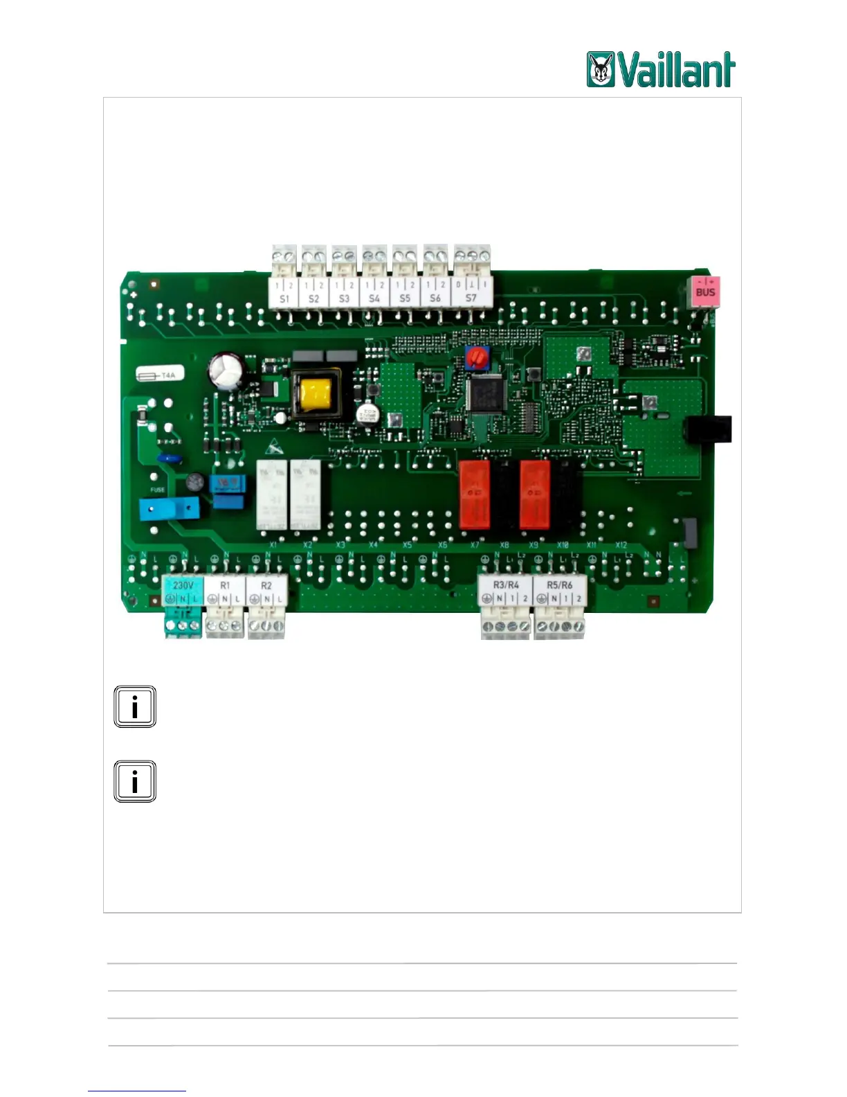
5.1.3.1 Terminal assignment for the VR 70 module
VR 70 printed circuit board
On contact "S7", "I" stands for Input and "O" for Output.
On outputs "R3/R4" and "R5/R6", "1" stands for Open and "2" for Closed.
The VR 70 configuration must be set in the controller's installer level (menu
item "Config.: VR 70 addr. 1") and not on the module's address switch.