multiMATIC 700/2
Notes
10/2015 93 Training 0020228700_00
In the event that a combination of "System diagram" and "VR 70 configuration" is se-
lected that is not permitted, the fault message "System diagram selection incorrect"
or "VR 70 configuration incorrect" is displayed on the controller.
If a combination of "System diagram" and "VR 71 configuration" is selected that is not
permitted, the fault message "System diagram selection incorrect" is displayed on
the controller.
Assignment of system diagrams to heat generators
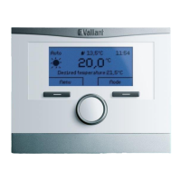
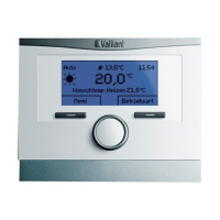
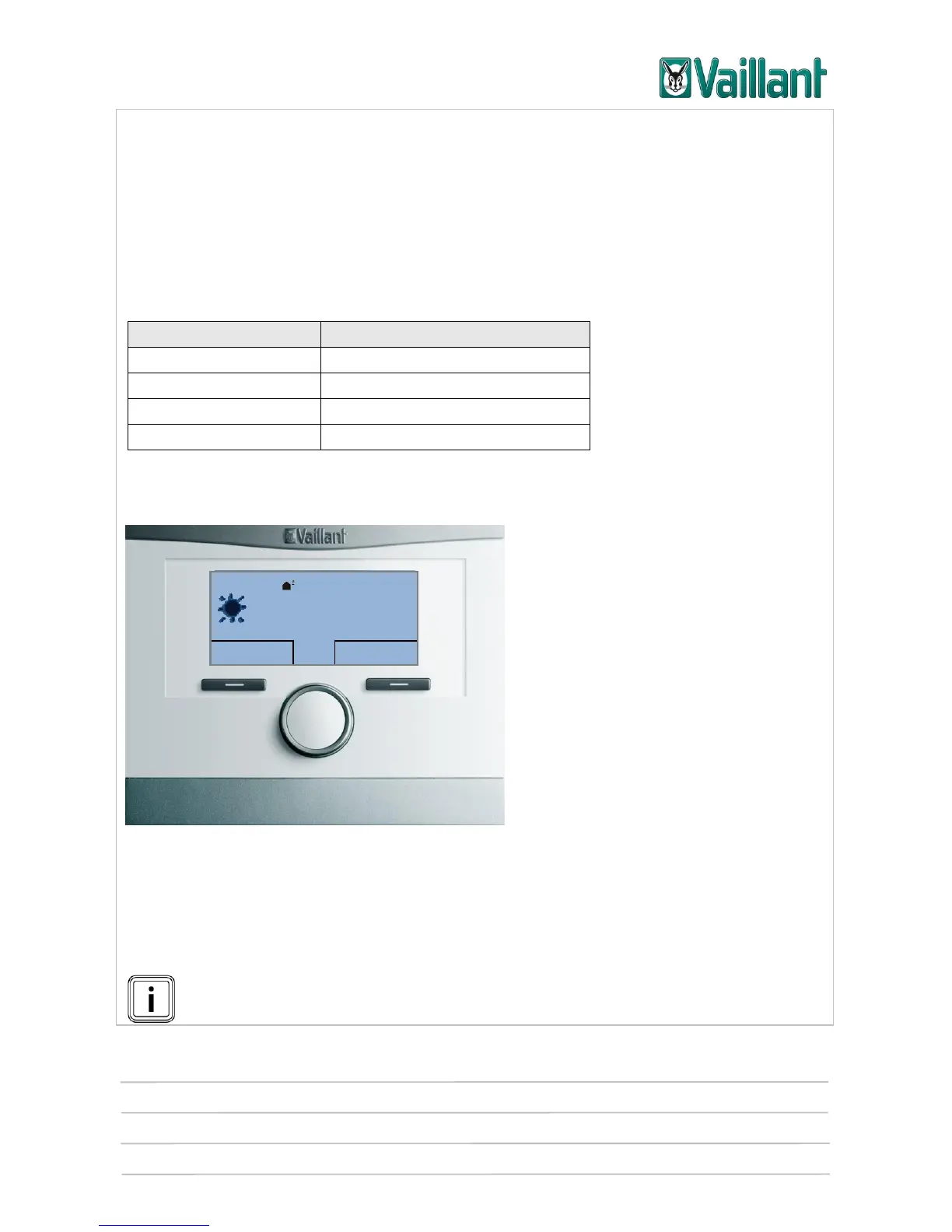
5.2.3 Settings and displays/indicators on the VR 91
Front view of the VR 91
The VR 91 remote control unit is a wire-bound remote control unit for one zone in
combination with the VRC 700 controller. It communicates with the boiler exclusively
via eBUS.
Only one VR 91 can be used in conjunction with VR 70.
Up to two VR 91 can be used in conjunction with VR 71.