multiMATIC 700/2
Notes
10/2015 88 Training 0020228700_00
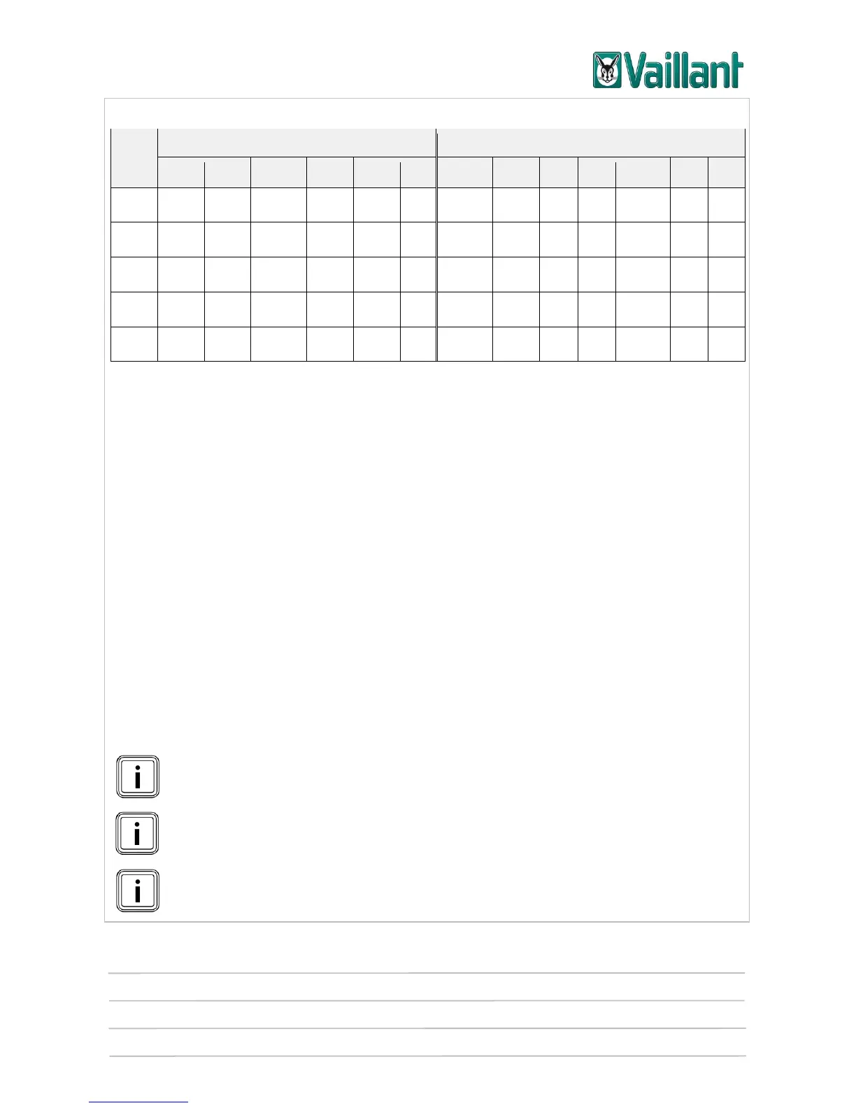
Overview of VR 70 configurations (1 – 12)
Assignment of the actuator outputs
Assignment of the sensor inputs
Heating pump for heating circuit 1
Top cylinder sensor for the buffer cylinder
Close mixer for heating circuit 1
Bottom cylinder temperature sensor for the buffer cylinder
Open mixer for heating circuit 1
Top cylinder temperature sensor for DHW section of allSTOR
buffer cylinder
External heating switch-off for heating circuit 1
Bottom cylinder temperature sensor for DHW section of all-
STOR buffer cylinder
Flow temperature sensor for heating circuit 1
Top cylinder temperature sensor for heating section of allSTOR
buffer cylinder
Heating pump for heating circuit 2
Bottom cylinder temperature sensor for heating section of
allSTOR buffer cylinder
Close mixer for heating circuit 2
First temperature sensor for ΔT control
Open mixer for heating circuit 2
Second temperature sensor for ΔT control
External heating switch-off for heating circuit 2
Output for an actuator for ΔT control
Flow temperature sensor for heating circuit 2
Charging pump or three-way valve switch to DHW cylinder
Cylinder temperature sensor
Collector temperature sensor
Bottom cylinder temperature sensor for DHW
cylinder
Legionella protection pump
System flow temperature (low loss header)
PWM actual value input and target value output of PWM pump
(only in conjunction with VMS 70 solar pump unit)
R3/R4, R5/R6: Mixer outputs -> only one of the outputs (1 or 2) can be
switched. It is not possible to switch both outputs at once.
A VR 11 sensor must be used for the "COL" sensor; a VR 10 sensor must be
used for all other sensors.
Closing the "DEM" contact ends the heating demand for the relevant heating
circuit.
*1
: VR 70 configurations 2, 4, 7, 8, 9, 10 and 11 are currently not supported.
Two VR 10 sensors are included in the scope of delivery for the VR 70.