2500 Automatic Tank Gauge
16 Installation and Operations Manual
Table 6: Tank Top Mounting — Installation Checklist
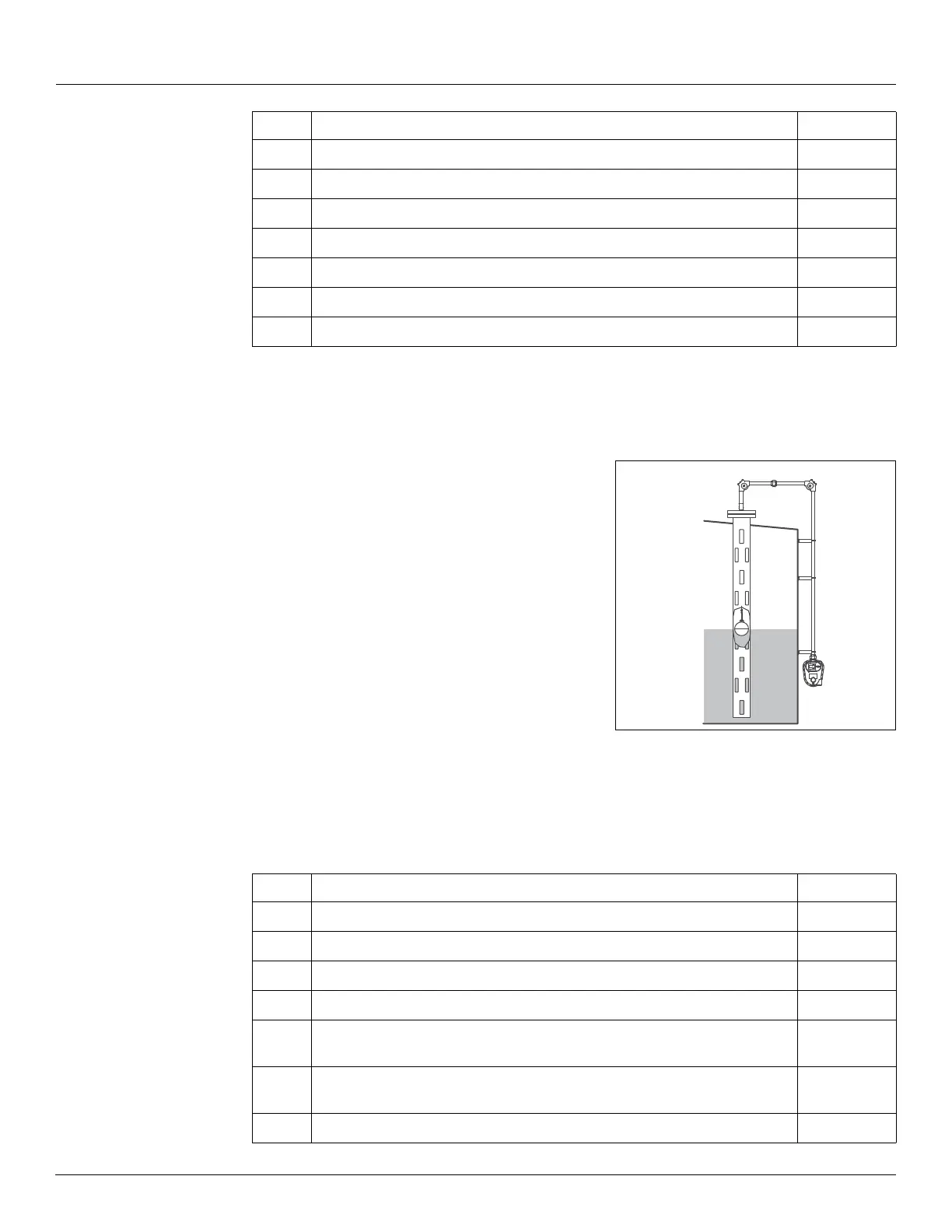
Stilling Well Service Cone Roof Tank 6" Diameter Float
Order Code T55, T56
Installation parts supplied include:
• 90° Elbow assembly (x2)
• Gauge 'U' bolt kit
• Support bracket (x6)
• gauge head and tape
• Float
• Tape connectors
Figure 10: Stilling Well Service Cone Roof Tank 6"
Diameter Float
Installation Checklist
When installing a 2500 ATG system on a Stilling Well Service Cone Roof Tank 6" Diameter Float,
complete each installation step below. Check off a step when it is complete. Refer to Section
“Installation Schematics” on page 21 for overall dimensions.
5
Section “Connecting the Tape to the Float” on page 30
6
Section “Install Tape in the Gauge Head” on page 35
7
Section “Reset the Counter” on page 40
8
Section “Calibrate the Counter” on page 41
9
Section “Initial Lubrication” on page 42
10
Section “Install a Transmitter and Replace all Covers” on page 42
11
Section “Initial Operation” on page 43
Step Description Complete
Step Description Complete
1
Section “Tank Roof Entry - Stilling Well” on page 25
2
Section “Installing Support Brackets & Pipework” on page 27
3
Section “Installing a Gauge Head at Grade Level” on page 28
4
Section “Float installation on an Out-of-Service Tank” on page 30
5
Section “Connecting the Tape to a 6" Interface Float in an 8" Stilling Well”
on page 33
6
Section “Feeding the Tape to a Gauge Head Located at Grade Level” on
page 34
7
Section “Install Tape in the Gauge Head” on page 35