2500 Automatic Tank Gauge
28 Installation and Operations Manual
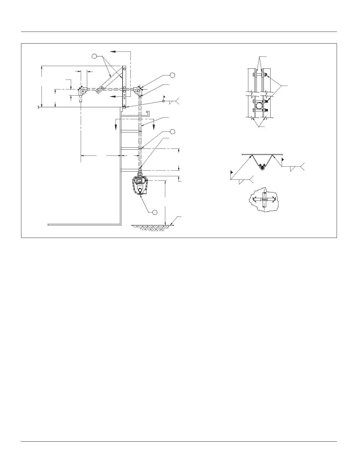
Figure 7: Example Support Bracket Installation
Installing a Gauge Head at Grade Level
Note Ensure you have completed all previous steps from your installation checklist
before proceeding.
Warning When removing the gauge head back cover, stand to one side as the last bolt is
removed. If the negator motor spring is broken, the broken pieces may cause injury when
the cover is removed.
1. Remove the back cover and gasket from the gauge head.
Note The weight of the installed gauge head is supported by the pipe and brackets.
2. Apply pipe thread compound and attach the gauge head to the exterior vertical pipe.
Position it for convenient reading.
.25
[6]
Convenient
eye level
Layout for pipe supports
spaced approximately at
10 foot [3 meter] intervals
47.75
[1213]
2[51] X 2[51] X .25[6.4]
Steel angle
View B - B
1
Maximum
36.00
[914]
16.00
[406]
Minimum
8.00
[203]
CC
72.00
[1829]
.25[6.4] X 1.5[38]
Steel flat bar
1/2-13 Hardware
4.50
[114]
4.50
[114]
7
B
B
Typical
View C - C
Grade
6.00
152]
.25
[6]
Tape / cable splice
at full tank
position
2 Places
1-1/2 Inch pipe and
fittings by customer
5
Typical
.25
[6]
Tape / cable splice
at empty tank
position
6