Varec, Inc. 43
Caution Do not over-torque the back cover bolts.
1. Remove the installation crank and thumbscrew.
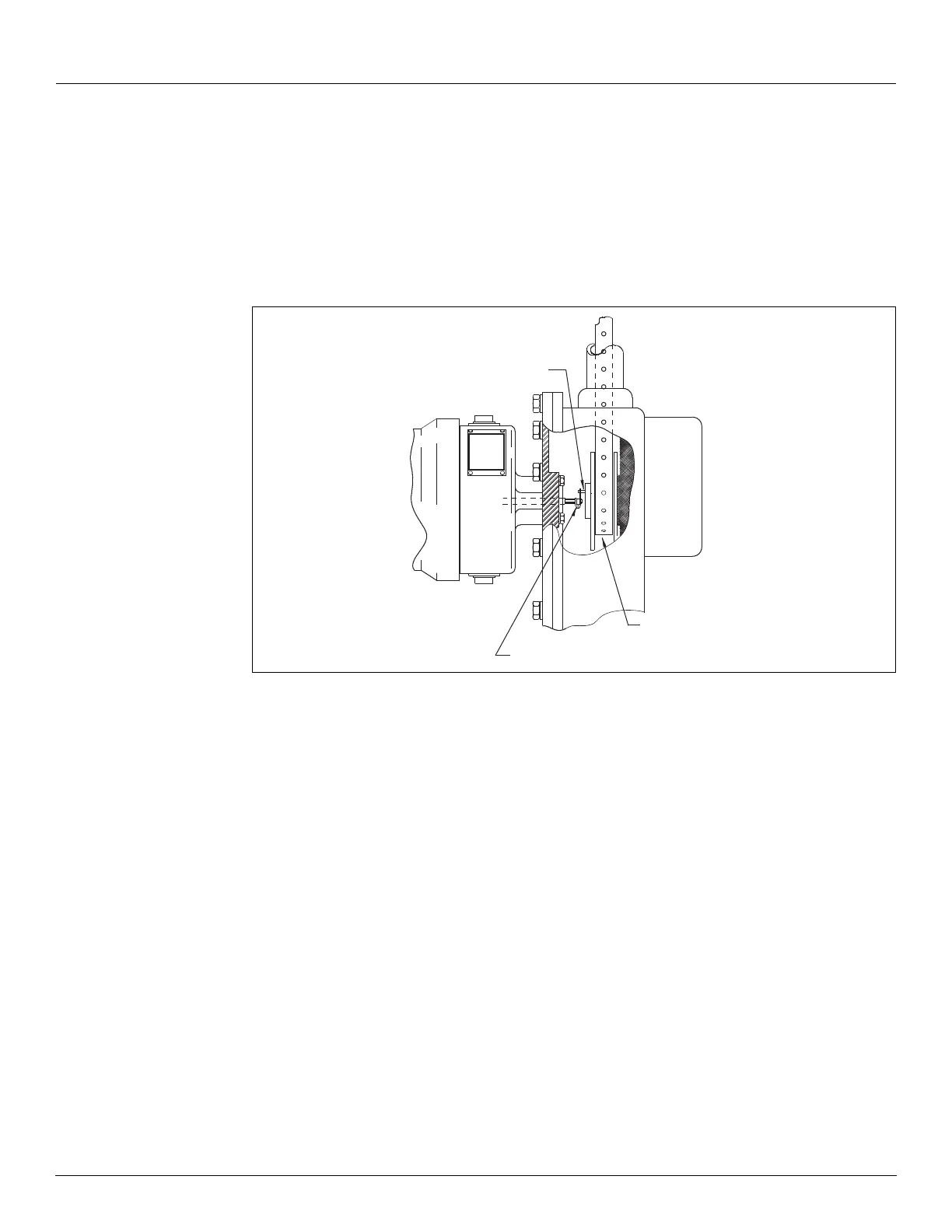
2. When a transmitter or other auxiliary equipment is to be installed, ensure the equipment
hole size and bolt pattern matches the 2500 ATG. Remove and discard the cap and red
fiber washers from the back cover. Each transmitter’s slotted coupling should properly
engage the sprocket sheave auxiliary drive pin. Use the cap screws to attach the transmit-
ter to the back cover. Refer to the transmitter documentation for detailed installation, con-
figuration, and operation.
Figure 17: Transmitter Installation on a 2500 ATG
Note The use of auxiliary units not manufactured or supplied by Varec will void any
Varec warranty and will relieve Varec of any obligation to service the product under war-
ranty.
3. Replace the back cover and its gasket.
4. Torque the back cover bolts to 6 ft-lb. Do not over-torque!
5. Replace the bolts, gaskets, and covers on the elbows.
6. Close the tank manholes and inspection covers.
7. Check the operation of the auxiliary unit as appropriate
Initial Operation
Caution Initial filling of the tank must be at a reduced rate of flow, until the float travel
and dial operation are verified. This checks that the 2500 ATG was installed correctly and
prevents possible damage to the gauge system. Floating Roof Tanks: On floating roof tanks
this is particularly important because the tape travel has not been checked during the
installation.
Sprocket, wheel,
and tape
Drive pin on sprocket
Gaugehead
Slotted drive coupling
Transmitter