Varec, Inc. 37
With a Negator Cassette
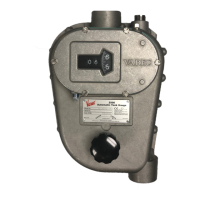
If you have a 2500 ATG with Negator Cassette, follow the procedure in this section to install
the gauge tape and load the negator cassette on the gauge head.
1. Install the furnished crank assembly and lock it into the case keyhole slot using the spring-
loaded screw.
2. Remove the two socket-head screws attaching the Negator Cassette to the storage sheave.
3. Remove the Negator Cassette from the gauge head by pulling it straight out.
Warning Do not overwind negator motor. Winding motor greater than the indicated
number of turns may cause the motor to dislodge and uncoil from its pulley, causing
damage to equipment and injury to personnel.
Warning Use both hands for a firm grasp on the crank while winding motor. Tighten
thumbscrew before releasing grip. The rapid unwinding of the spring could result in the
crank spinning and striking the operator.
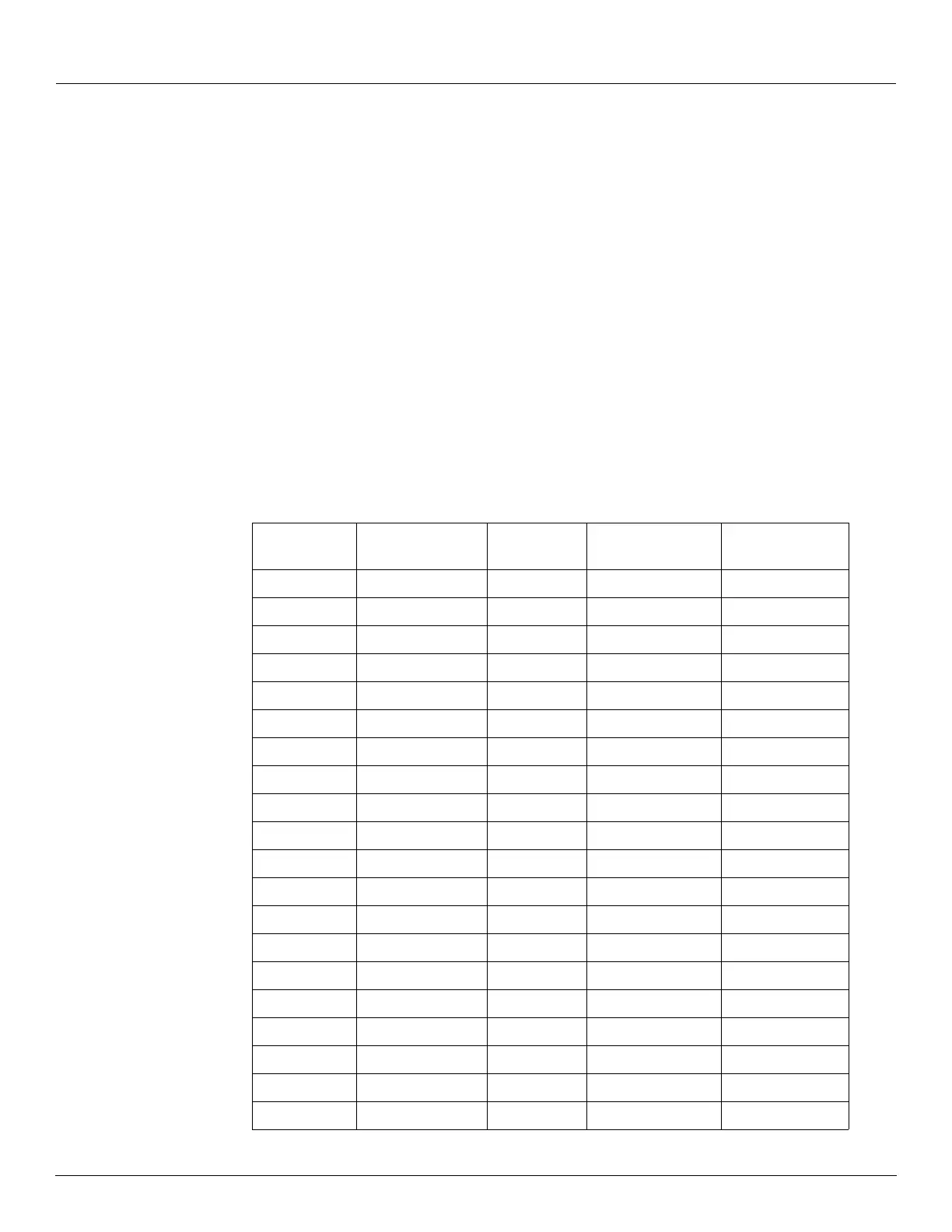
4. Grasp the crank assembly handle and unlock it from the Negator Cassette. Wind the motor
clockwise. The number of turns is indicated in Table 2, in accordance with the level.
Innage Tank
Level (ft)
Innage Tank Level
(m)
Outage Tank
Level (ft)
Outage Tank Level
(m)
Number of Turns
(Neg. Cassette)
0 0.0 66 20.1 45
2 0.6 64 19.5 44
4 1.2 62 18.9 43
6 1.8 60 18.3 41
8 2.4 58 17.7 40
10 3.0 56 17.1 39
12 3.7 54 16.5 37
14 4.3 52 15.8 36
16 4.9 50 15.2 35
18 5.5 48 14.6 33
20 6.1 46 14.0 32
22 6.7 44 13.4 31
24 7.3 42 12.8 29
26 7.9 40 12.2 28
28 8.5 38 11.6 27
30 9.1 36 11.0 25
32 9.8 34 10.4 24
34 10.4 32 9.8 23
36 11.0 30 9.1 22
38 11.6 28 8.5 20
Table 2: Innage and Outage Turns of the Negator Cassette