EasyManua.ls Logo

Varec 2500 User Manual

Varec 2500
124 pages
To Next Page IconTo Next Page
Page #1 background imageLoading...
Page #1 background image
IOM001GVAE1117
Automation Solutions for oil & gas, defense and aviation applications
Installation and Operations Manual
Dispatch and Fuels Accounting
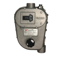
2500 Automatic Tank Gauge
Mechanically operated, float and tape gauges
for continuous liquid-level measurement in
bulk storage tanks

Table of Contents

Questions and Answers:

Varec 2500 Specifications

General IconGeneral
BrandVarec
Model2500
CategoryAccessories
LanguageEnglish

Summary

Introduction

Getting Acquainted with the 2500 Automatic Tank Gauge Systems

Overview of the 2500 ATG systems, their function, and installation options.

Tank Gauge Operation

Explains how the 2500 ATG uses a float and tape to measure liquid level.

Calibration and Volume Measurement

Discusses factors affecting measurement accuracy and calibration.

Product Options

Details available measurement configurations like English fractional/decimal and metric.

General Preparation

Safety Precautions

Emphasizes reviewing safety precautions before installation.

Tools, Equipment, and Materials

Lists user-supplied tools, equipment, and materials needed for installation.

Floating Roof Tank Installations

Provides recommendations for installing gauges in floating roof tanks.

Support Brackets

Explains the function and placement of support brackets for conduit.

Installation

Installation Schematics

Provides diagrams illustrating various 2500 ATG installation types.

Tank Roof Entry - Cone Roof Tank

Instructions for creating roof openings for cone roof tank installations.

Installing Anchors and Guide Wires

Details the process of installing top and bottom cable anchors and guide wires.

Installing a Gauge Head at Grade Level

Step-by-step guide for attaching the gauge head at ground level.

Connecting the Tape to the Float

Instructions for connecting the tape to the float, including forming a 'U'.

In-Service Installation Procedures

Negator Cassette Installation

Covers the installation of the negator cassette for motor protection.

Disassembly

Steps to prepare the gauge head for negator cassette installation.

Assembly

Steps to reassemble the gauge head with the negator cassette.

In-service Float & Guide Wire Installation

Guide for installing floats and guide wires in an in-service tank.

Operation

Operation Check

How to check gauge operation using the gauge check knob.

Gauge Head Disassembly and Re-assembly

Gauge Head Disassembly

Detailed steps for disassembling the 2500 ATG gauge head.

Gauge Head Assembly

Comprehensive guide for reassembling the gauge head.

Counter Wheel Assembly

Procedures for assembling and verifying the counter wheel mechanism.

Maintenance Routines

Calibration Check

How to check gauge accuracy against a hand dip measurement.

Lubrication

Guidance on lubricating gauge head parts and recommended lubricants.

Spare Parts and Maintenance Kits

Gauge Head Spare Parts

Lists individual spare parts for the 2500 ATG gauge head.

Troubleshooting

Dials Do Not Respond When Gauge Check Knob is Rotated

Identifies causes and solutions for unresponsive dials.

Calibration Repeatability Unstable

Addresses issues with unstable calibration readings.

Specifications and Reference Data

2500 ATG Gauge Head

Details materials used in the gauge head construction.

2500 ATG Product Dimensions

Provides dimensional drawings for Type B and Type C gauge heads.

Order Codes

Aluminum Gauge Head – English Configuration – Negator Motor

Lists order codes for this specific gauge head configuration.

Iron Gauge Head – English Configuration

Lists order codes for English configuration iron gauge heads.

Aluminum Gauge Head – English Configuration – Negator Cassette

Lists order codes for English negator cassette gauge heads.