2500 Automatic Tank Gauge
34 Installation and Operations Manual
11. Lower the float down the stilling well so that is rests at the bottom of the tank/well
(lowest measuring point).
12. Make certain that the tape is not kinked or twisted.
13. Replace the flange onto the stilling well and bolt down.
Feeding the Tape to a Gauge Head Located at Grade
Level
Note Ensure you have completed all previous steps from your installation checklist
before proceeding.
Note At this point the tape/cable should be connected to the float.
Note The following steps explain how to feed the tape through the conduit from the
tank entry point or roof position to the gauge head at grade level.
1. Spread a clean ground cloth below the gauge head and remove the lower tape hole pipe
plug.
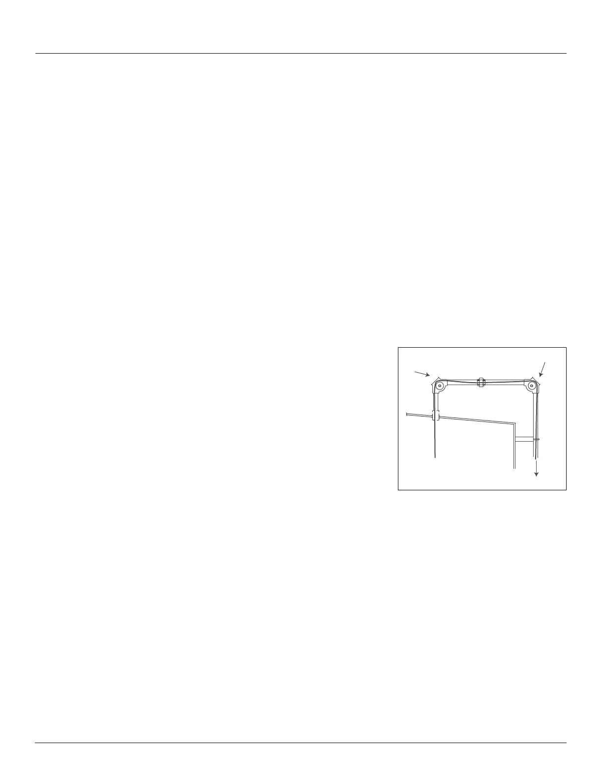
2. Feed the other end of the tape over the tank
entry elbow sheave, through the horizontal pipe
(3), and over the sheave in the outboard elbow.
3. Lower the tape through the exterior pipe
(4) and
down through the gauge head and lower tape
hole, then onto the ground cloth
(5) until the tape
is unrolled. Make sure that the tape does not
become kinked or dirty.
4. Check the perforated tape length and trim, if nec-
essary.
Figure 13: Feed the Tape Through the
Conduit to the Gauge Head
Note Trimming the tape shorter than 6 feet could result in the tape end retracting up
into the conduit.
5. If the tape extends more than 6 feet (1.8 M) below the gauge head when it is at zero level,
trim the excess. Trim the tape about 6 feet (1.8 M) from the bottom of the gauge head.
6. To install the perforated tape in the gauge head, proceed to the section for your type of
gauge head:
• For a Standard 2500 ATG with a Negator Spring Motor, go to “With a Negator
Spring Motor” on page 36.
• For a 2500 ATG with Negator Cassette, go to “With a Negator Cassette” on
page 37.
• For a Hand Crank Type Gauge Head Installation, go to “With a Hand Crank Gauge
Head” on page 38.
3
4
5