2500 Automatic Tank Gauge
40 Installation and Operations Manual
3. To adjust, loosen the screws on the cable clamp while holding on to the cable. Pull the
cable through the clips while keeping the tape tension tight. When splice is in proper posi-
tion, tighten the screws and release cable. The spring motor will pull the tape taut.
4. Check that the float is correctly positioned parallel to the waterline of the well, then cut
off the excess cable.
Caution Do not allow the float to fall back to the floor of the tank. Damage to the float
or tank may result.
Reset the Counter
Note Ensure you have completed all previous steps from your installation checklist
before proceeding.
To reset the dial and counter, remove the counter cover assembly as shown and described in
this section.
Caution Be careful not to pull up and disengage or drop the pinion gear
(24). If the pinion
gear is disengaged, it may be necessary to disassemble and reassemble the counter mech-
anism to properly calibrate the gauge. If this becomes necessary, refer to “Counter Wheel
Assembly," in the Service Manual.
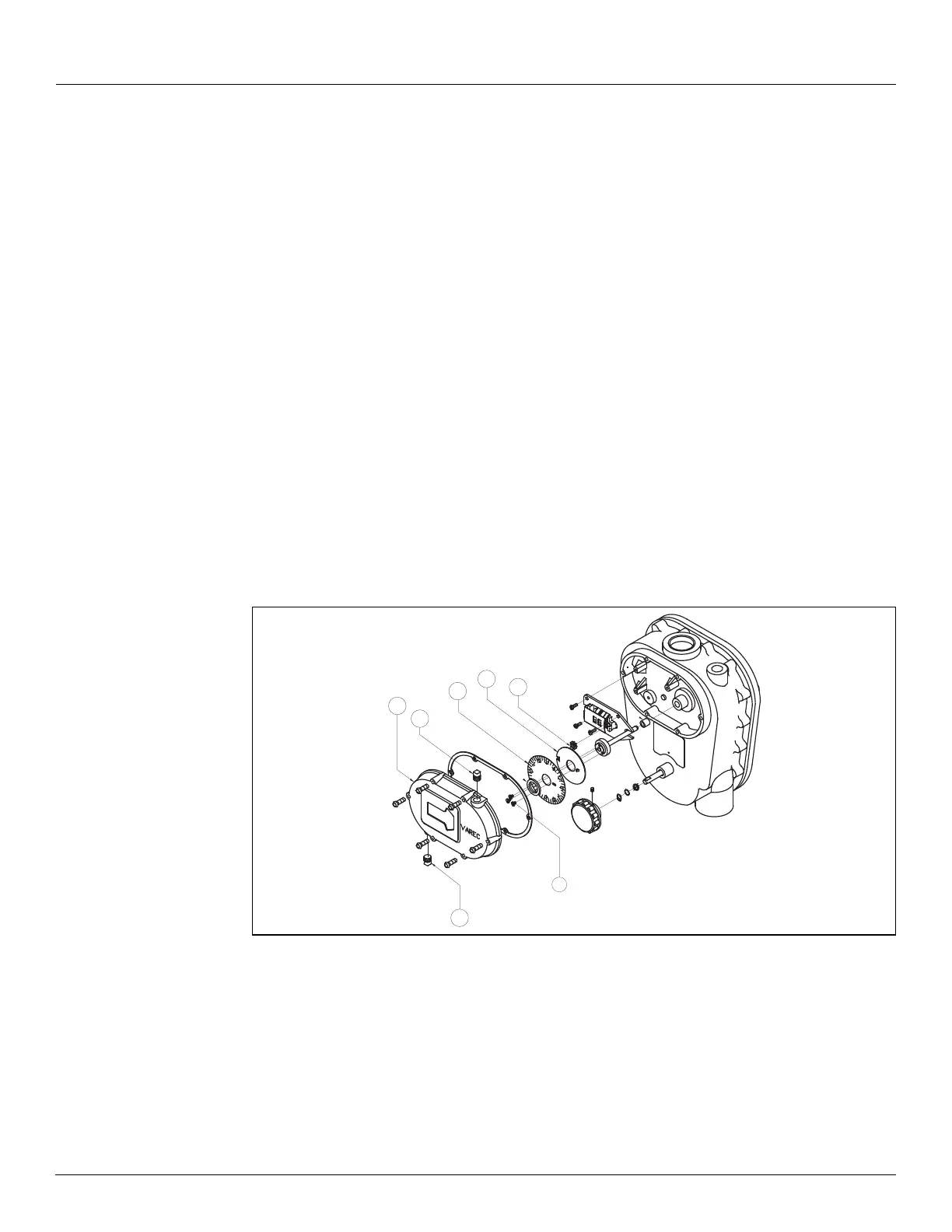
Figure 15: 2500 ATG Counter Cover and Assembly Parts
Note Reversible dials - English gauge heads are shipped with a dial indicating in feet,
inches, and 1/16 inch. The backside of the dial is marked to indicate 1/10 ft. x 1/100 foot.
The user can reverse the dial to suit.
1. Remove the counter assembly cover.
2. Rotate dial plate
(7) and gear (5) until the dial plate and counters display all zeros.
3. Loosen dial plate screws
(40) until the dial plate (7) and gear (5) rotate freely and inde-
pendently of the hub assembly.
19
53
54
40
7
5
24