2500 Automatic Tank Gauge
66 Installation and Operations Manual
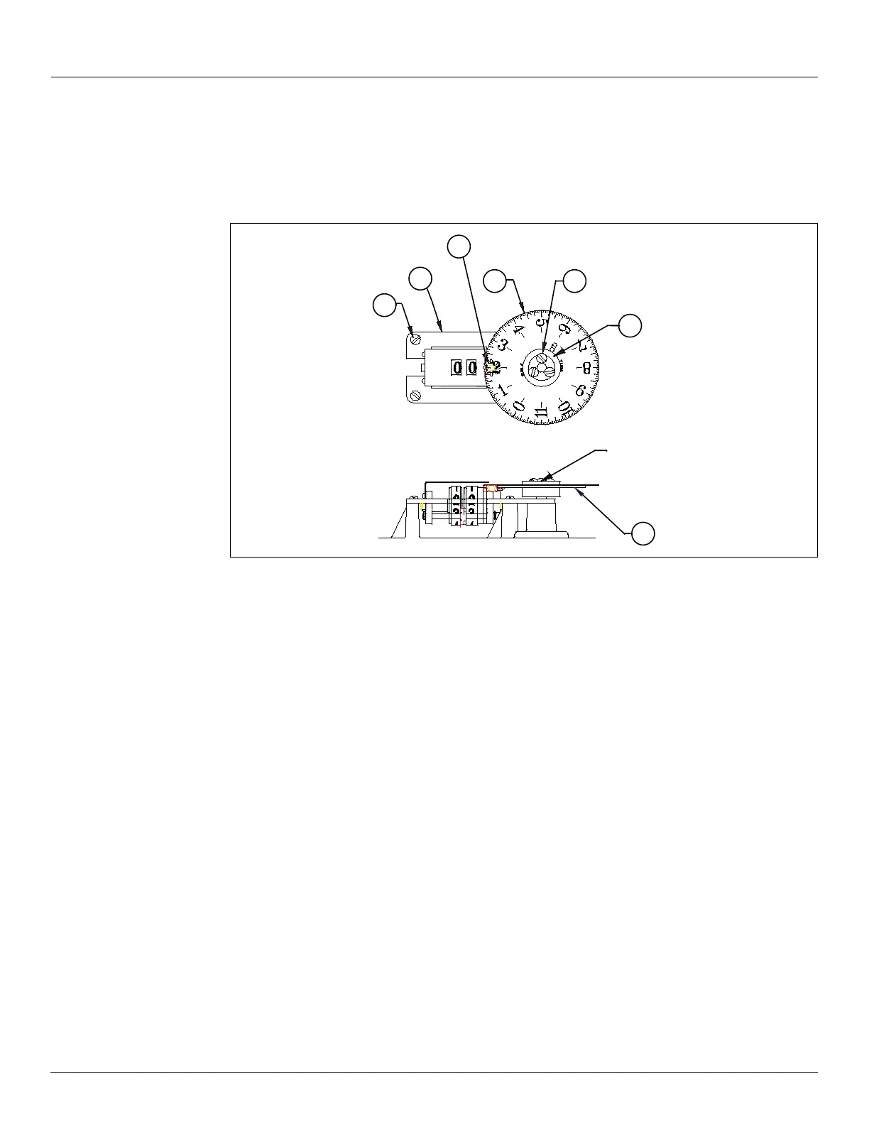
Counter Wheel Assembly
If you remove the screws (43) and retainer from the counter wheel assembly (21) and the pinion
gear
(24) is disengaged, you must remove the dial and pinion gear in order to reset the counter
drums and dial
(7) to zero or to the calibrated liquid level.
Figure 10: Counter Wheel Assembly
1. Place counter assembly (21) on supports and loosely install three mounting screws (43).
• Do not tighten the screws.
2. With the pinion gear removed, rotate the counter assembly drums to display a whole
number.
• The red-tipped pointer will be aligned with the center point between two teeth on
the counter drum gear.
3. Examine the pinion gear. Note that from the top side, alternate teeth are high or low. From
the bottom side, the 8 teeth are evenly aligned.
4. With right thumb and finger, pick up the pinion gear by two of the high teeth and with the
top side facing up.
5. Install the pinion gear on the counter base shaft.
• Set the gear with the 8-tooth side down against the counter base and so that the
left-facing low tooth fits between two teeth of the counter drum gear.
Note The tops of the three teeth (1 pinion gear tooth and 2 counter drum gear teeth)
should be aligned. If they are not, you may have set the pinion gear 1/2 notch out of
position, and the counter display will also be off by that much.
6. Set the dial gear on the dial assembly hub without meshing the pinion gear teeth.
• Set the dial gear with its tooth up, and turned away from the pinion gear.
Note To ensure the correct horizontal clearance, keep the dial gear tooth away from the
pinion gear until step 9.
24
7
40
5
Hub Assembly
21
43
9