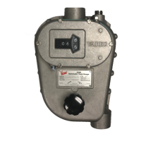
2500 Automatic Tank Gauge
36 Installation and Operations Manual
Warning Do not overwind negator motor. Winding motor greater than the indicated
number of turns may cause the motor to dislodge and uncoil from its pulley, causing
damage to equipment and injury to personnel.
Warning Use both hands for a firm grasp on the crank while winding motor. Tighten
thumbscrew before releasing grip. The rapid unwinding of the spring could result in the
crank spinning and striking the operator.
Caution Do not allow the float to fall back to the floor of the tank. Damage to the float
or tank may result.
Note Be sure to remove the installation crank when installation is complete. Do not
store the crank or the thumbscrew in the gauge head. Put them in a storage area for safe
keeping and future use.
With a Negator Spring Motor
1. If you have a Standard 2500 ATG with a Negator Spring Motor, follow the procedure in this
section to install the gauge tape and load the negator motor on the gauge head.
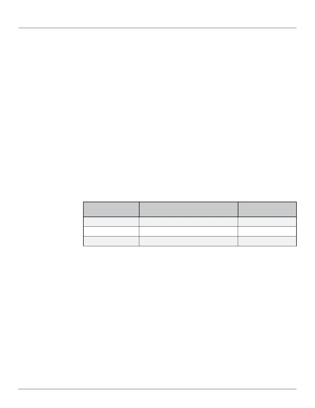
2. Attach the furnished installation crank and thumbscrew to the tape storage sheave.
Wind the storage sheave clockwise, the number of turns indicated in Table 1, and then
securely tighten the thumbscrew.
Table 1: Turns to Wind Negator Motor
3. If you have a hand crank type gauge head, ensure that the motor is wound and the ratchet
pawl is at mid position (engaged).
4. At the gauge head, put the first hole in the tape on a pin of the sprocket close to the tape
guide.
5. Rotate the sprocket clockwise to pull the tape through the guide.
6. Pull the tape around the storage sheave.
7. Fasten the 2rd hole in the tape to the tape storage sheave on the sheave pin.
8. Hold the installation crank firmly and loosen the thumbscrew.
9. While keeping tension on the tape, allow the motor to wind the excess tape counter-clock-
wise around the storage sheave until all slack is removed.
10. Check the tape path between the float and the gauge head to be sure that it is not kinked
or twisted.
Note If you are installing a hand crank type gauge head, proceed now to section , step 4.
Motor Sheave Part
No.
Gauge Head Motor (Normal Application) Turns w/2500 ATG
BA7762
Standard: 0 - 60' (0-18m) tank range
45
BA17725
Extra Strong: 0 - 60' (0-18m) tank range
47
BA17087
Extra Long: 0 - 90' (0-27m) tank range
63