2500 Automatic Tank Gauge
18 Installation and Operations Manual
Table 8: External Floating Roof Tank and Floatwell — Installation Checklist
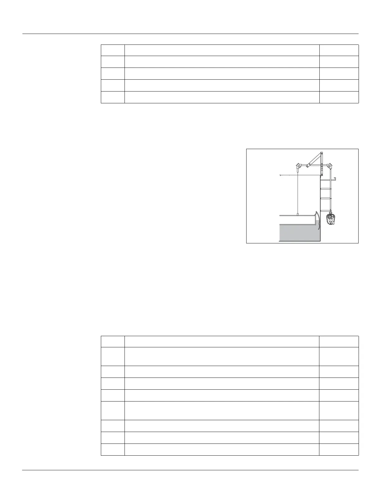
External Floating Roof Tank: No Floatwell
Order Code T06, T16
Installation parts supplied include:
• 90° Elbow assembly (x2)
• Gauge 'U' bolt kit
• Support bracket assembly
• Support bracket (x6)
• gauge head and tape/cable
• Tape/cable connectors
Figure 12: External Floating Roof Tank: No Floatwell
Installation Checklist
When installing a 2500 ATG system on a cone roof tank, complete each installation step below.
Check off a step when it is complete. Refer to Section “Installation Schematics” on page 21 for
overall dimensions.
Note Due to the resulting gross measurement inaccuracies, Varec does not recommend
that the perforated tape/tape cable be attached directly to a floating pan. Use a covered
floatwell for the best measurement accuracy.
10
Section “Calibrate the Counter” on page 41
11
Section “Initial Lubrication” on page 42
12
Section “Install a Transmitter and Replace all Covers” on page 42
13
Section “Initial Operation” on page 43
Step Description Complete
Step Description Complete
1
Section “Correct Float Positioning for an External Floating Pan Installation”
on page 25
2
Section “Installing Support Brackets & Pipework” on page 27
3
Section “Installing a Gauge Head at Grade Level” on page 28
4
Section “Connecting the Cable to a Floating Pan” on page 33
5
Section “Feeding the Tape to a Gauge Head Located at Grade Level” on
page 34
6
Section “Install Tape in the Gauge Head” on page 35
7
Section “Reset the Counter” on page 40
8
Section “Calibrate the Counter” on page 41