Varec, Inc. 23
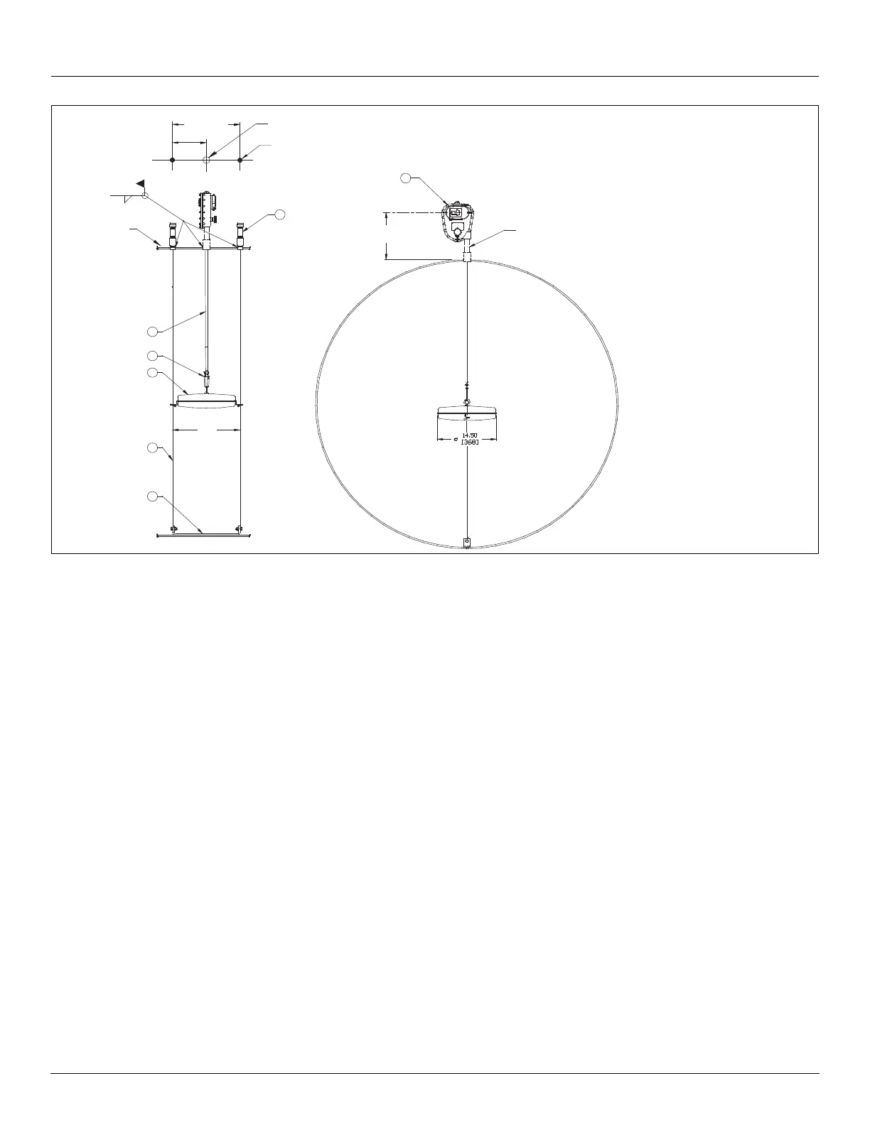
Figure 4: Horizontal Bullet Tank with Roof Reading Gauge
Tank Roof Entry - Cone Roof Tank
Note Ensure you have completed all previous steps from your installation checklist
before proceeding.
Note Varec recommends the installation of a manhole cover as shown in Figure 1 on
page 46
1. Determine the position on the tank roof beneath which the center of the float will rise and
fall (Measuring Point). Notice that this position is located a minimum of 16 inches (406
mm) and a maximum of 36.00 inches (914 mm) from the wall of the tank.
2. Provide the roof holes centered on this position. For installations without guide wires only
the center hole for the tape pipe is required.
• The float diameter is 14.50 inches (368 mm). The guide cable holes are centered
8.50 inches (216 mm), each side of the center of the float.
3. If performing a Bolted Cone Roof type installation, check the angle of the roof. The sup-
plied mounting bracket for the gauge head is designed for a 1/12 roof pitch (1 inch [25
mm] rise over 12 in [300 mm] run).
4. Screw the “drop” pipe coupling into the vertical pipe nipple. This will aid in positioning the
coupling, while welding.
7
9
4
2
3
17.00
[432]
Tank
roof
.25
[6]
Convenient
height
1
1-1/2 Inch NPT pipe nipple
furnished by customer
1. Gaugehead
2. Float
3. Tape
4. Tape/Cable fastener
6. Top Anchor
7. Bottom Anchor
9. Float Guide Cable
Unless otherwise noted
dimensions in inches (millimeters).
All welding by customer.
6
17.00
[432]
8.50
[216]
1-1/2 Inch NPT coupling
furnished by customer
2x Ø1.75 [44] hole