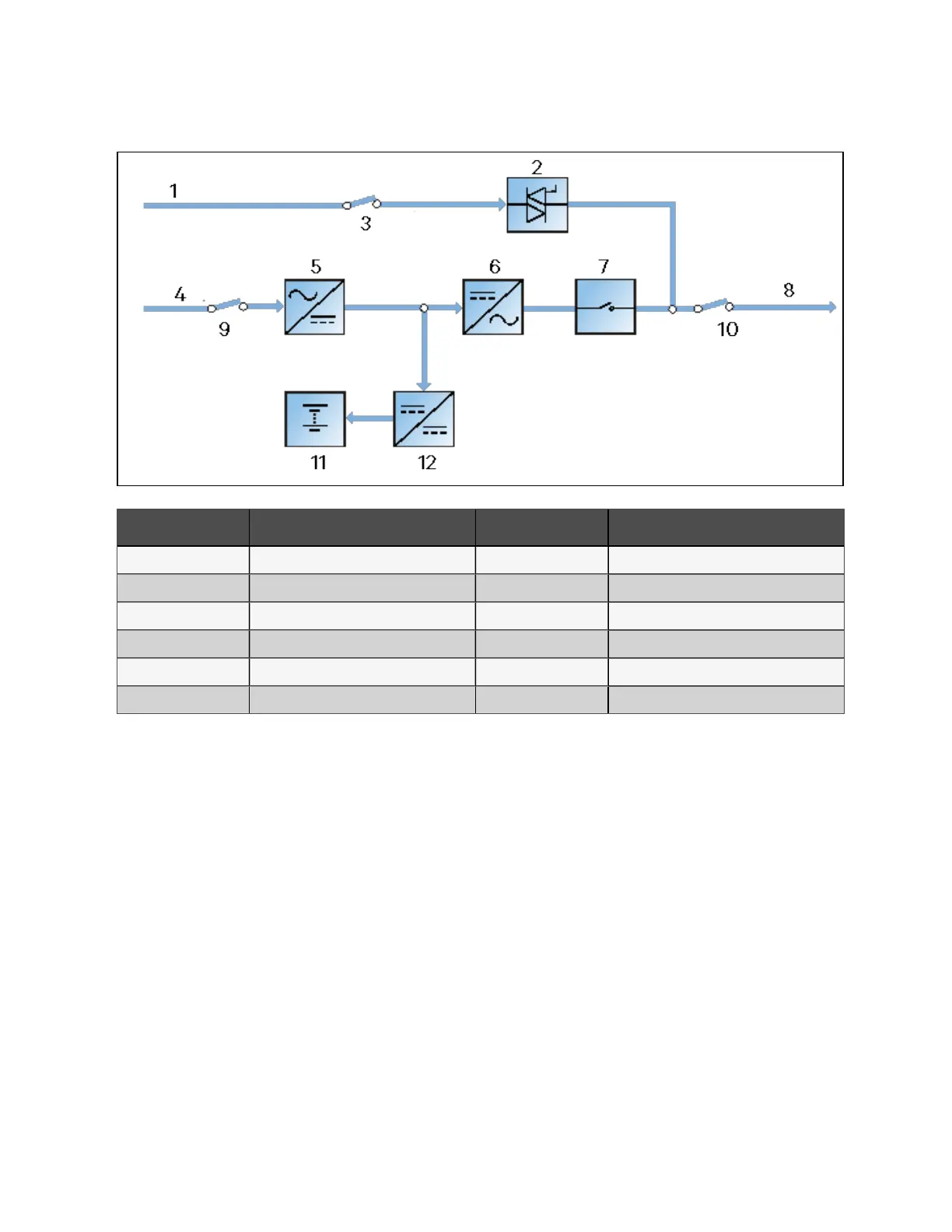
Figure 2.8 Bypass dyn am ic regulation m ode
N O. D esc rip tio n N O. D esc rip tio n
1 Bypass input 7 Inverter switch
2 Static switch 8 UPS output
3 Bypass input switch 9 Rectifier input switch
4 Mains input 10 Output switch
5 Rectifier 11 Battery
6 Inverter 12 Battery charger
2 Overview
19
Vertiv™ Liebert® EXM2 UPS User Manual