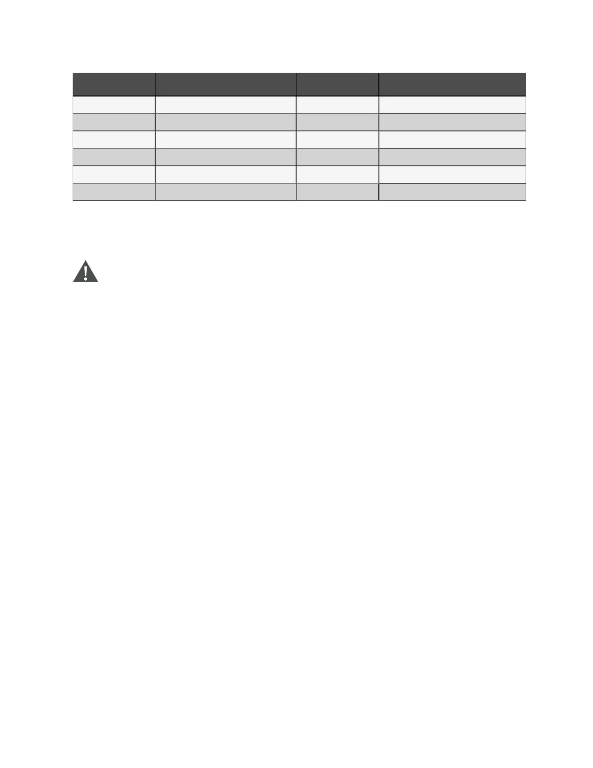
N O. D esc rip tio n N O. D esc rip tio n
1 Bypass input 7 Inverter switch
2 Static switch 8 UPS output
3 Bypass input switch 9 Rectifier input switch
4 Mains input 10 Output switch
5 Rectifier 11 Battery
6 Inverter 12 Battery charger
If ECO mode is required, adjust corresponding parameters through the operator control and display panel.
The operation method of ECO mode is the same as the description in Single UPS Operation Introduction . However, in normal
mode, the load is powered by the bypass, the TOUCHSCREEN displays 'Bypass mode'.
W A RN IN G! In EC O m ode, the load is not protected against m ains distortion.
Parallel redundan cy m o d e (system expansion)
For higher capacity or higher reliability, the outputs of multiple UPS modules can be programmed for directly paralleling while
a built-in parallel controller in each UPS module ensures automatic load sharing. The parallel system can be composed of up
to six UPS modules. For the operation principle diagram of the parallel redundancy mode, see Figure 8.1 on page140.
Frequency converter m ode
The UPS can be programmed into frequency converter mode for either 50Hz or 60Hz stable output frequency. The input
frequency may vary from 40Hz to 70Hz. Under this mode, it is required to open the maintenance bypass switch to disable the
static bypass operation, and the battery becomes optional depending on any requirement to operate in battery mode.
LBS m o d e
A dual bus system consists of two independent UPS systems, each containing one or more parallel UPS modules. The dual
bus system has high reliability and is applicable to the load with multiple inputs. For single-input load, an STS can be installed
to power the load. For the operation principle diagram of the LBS mode, see Figure 8.5 on page148 and Figure 8.6 on
page149.
Dynamic regulation mode
As shown in Figure 2.8 on the facing page, if this mode is selected, all power switches and the battery switches are closed
except for the maintenance bypass switch, and the system prefers to put the load on the bypass, to achieve the aim of
energy-saving. When the load power is fed by bypass supply, the inverter is in the mode of power quality compensation for the
bypass voltage. When the voltage of the bypass supply is beyond the predefined and adjustable limits, the system will transfer
to the inverter output. In this mode, the system can normally charge the battery.
2 Overview
18
Vertiv™ Liebert® EXM2 UPS User Manual