VI.BE.MAC.S.p.A.
pag.12
12. CHANGING THE EQUIPMENT
The V3Unit, using a quick change, allows the operator to change, in a simple way, the fitting in the machine
for another optional fitting for carrying out a different operation.
Three different working patterns for the unit can be selected.
With a special eyelet containing a "key" and with the two clamping screws of the fitting, it can be changed
maintaining its position perfectly in respect to the regulation carried out by the manufacturer.
NOTE: Under no circumstances loosen the clamping screws of the key positioned on the Y axis carriage,
which keeps the fitting perfectly aligned.
12.1.FROM THE DESIGN TO THE LABEL.
First STOP the machine using the specific instruction
Remove the material pressure foot by loosening the clamping screw.
Remove the design form by loosening the two clamping knobs (A) on the equipment brackets.
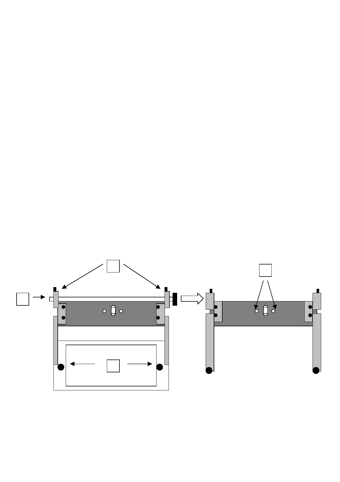
Loosen the two clamping screws (B) on the side supports of the transversal shaft of the equipment with a
2.5mm Allen key.
Take off the shaft (C) from the two supports.
Loosen the two clamping screws of the equipment (D) at the Y axis carriage with a 4mm Allen key.
Take out the equipment from its location
Loosen the two clamping screws (E) of the pneumatic connector (OCTOPORTA)
Loosen the two retaining springs of the working surface (F), using the two small levers (G) under the surface.
Manually un-hook the mobile part of the retaining spring from the clamping pin (H), on the right and left side
of the sewing machine.
Place the equipment on the working plane
Take out the working surface from the two tapered locations. If the two guides are difficult to get out, push
the surface downwards delicately and then pull gently.
Now the machine appears as only the sewing head.
Place the fitting for labels on the head, with the “key” eyelet positioned above it.
Insert gently the “key” in the eyelet (L) placed on the lower support.
Tighten the two clamping screws (D) of the pneumatic connector (OCTOPORTA).
Tighten the two clamping screws of the equipment (C) at the Y axis carriage with a 4mm Allen key.
Insert the shaft (B) in the two supports.
Tighten the two clamping screws on the two side supports (A) of the equipment transversal shaft with a
2.5mm Allen key.
B